Computer controlled machining
Table of content:
1 - Individual Assignment1.1 - Designing the origami door (cardboard) 1.2 - Cutting and assembling the origami door (cardboard) 1.3 - Designing the origami door (plywood) 1.4 - Generating the toolpath 1.5 - Onto the machine 1.6 - Attempt to make the cylindrical wooden rod 1.7 - Assembly
2 - Group assignment
Individual asisgnment
In this week of Computer controlled machining, we had to make something big(in meter scale) of wood from the CNC Router MAchine.
A long back I came accross this video and since then i wanted to make this,
https://www.youtube.com/watch?v=XnNk647Ko0E
Original Creator of this concept:
https://www.instagram.com/warwickturvey/
I did understand the concept of the origami door by seeing that video.
I then came accross this video, which helped me a lot with making the prototype of the door,
https://www.youtube.com/watch?v=Fu0GyFCLT0Y&t=0s
Designing the origami door (cardboard)
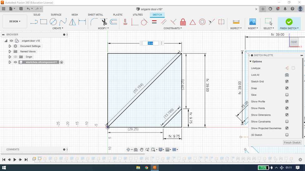
With all the things clear in my mind, I started the design in Fusion 360. I wanted to first try it out onto the cardboard so i designed the
model with parametric design so i just need to scale up if the concept works.
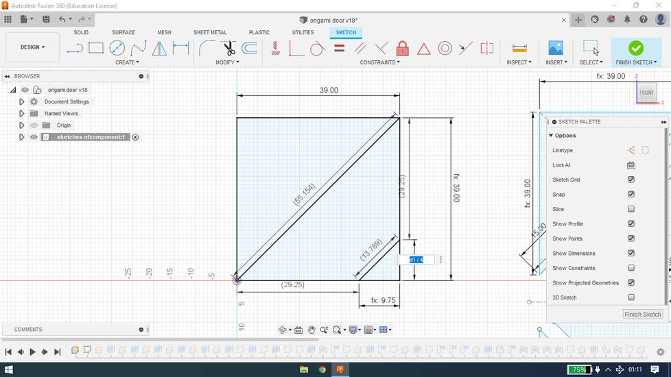
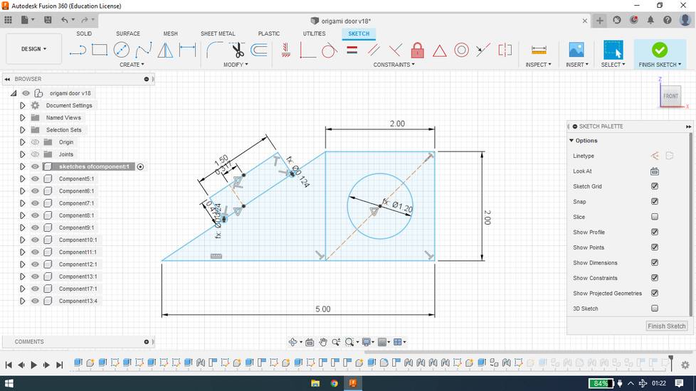
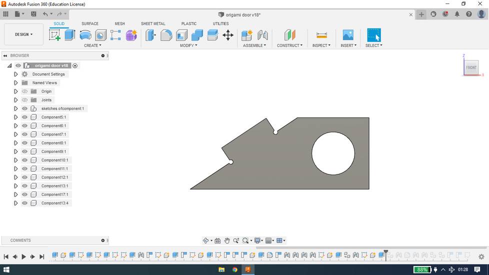
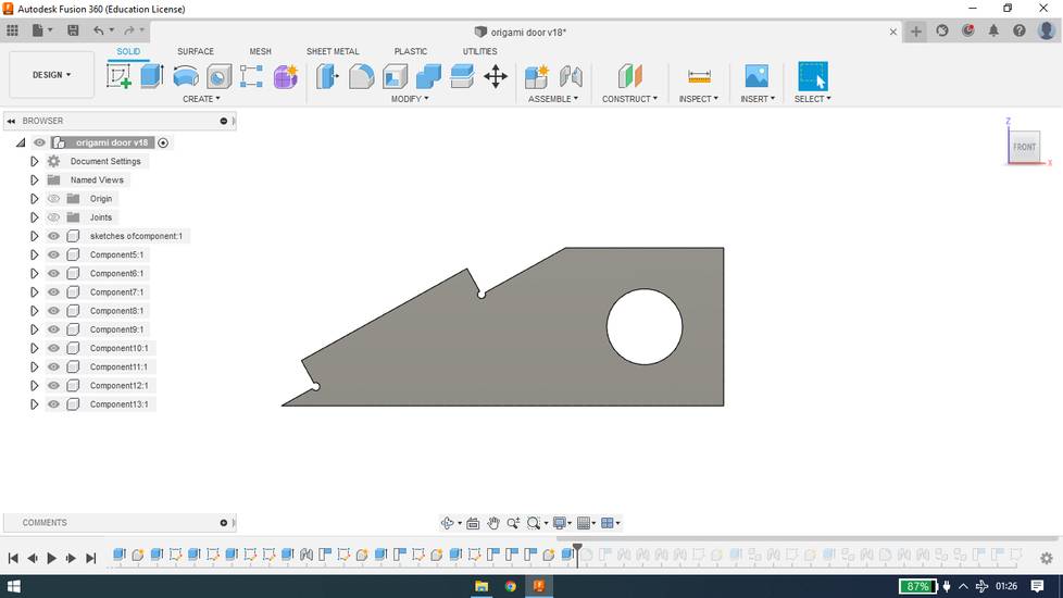
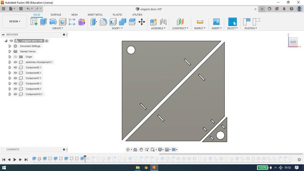
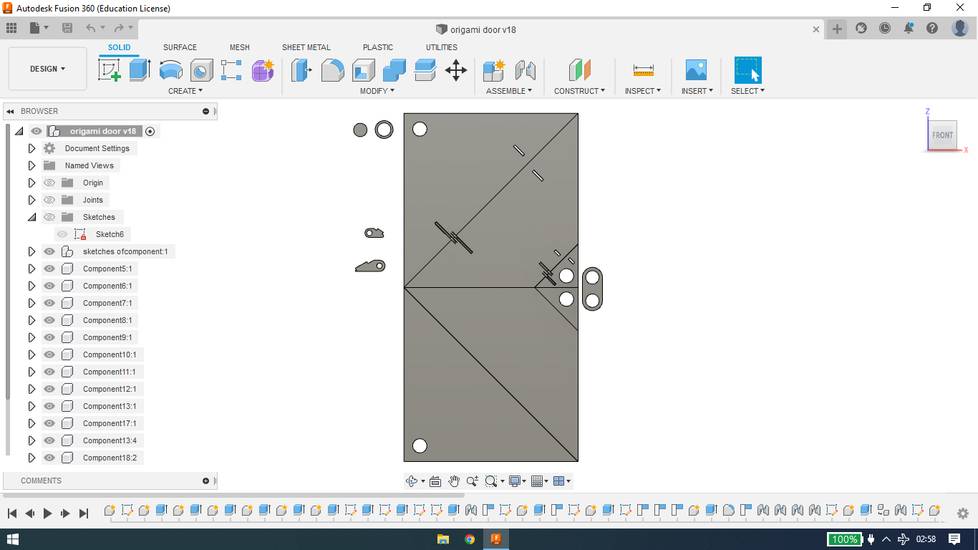
The upper square and the bottom square needs t be symmetric, so i designed the upper part, cut that square into three section
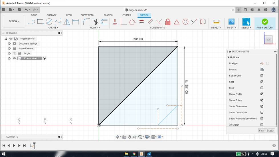
i took the reference of the midpoints to make that 3rd small triangle, but the easy way is to assign them the dimension which is 1/4th of the
length of the square, like this
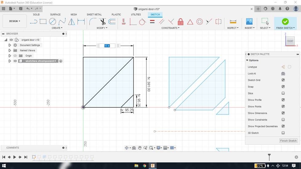
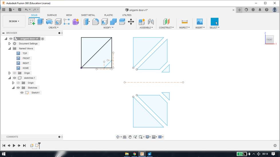
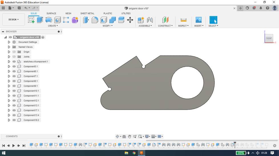
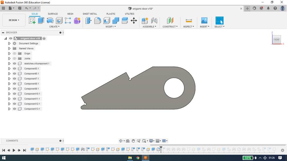
then i copied the sections and pasted it, and with the mirror function, the door was ready, without pivot joints and hinges
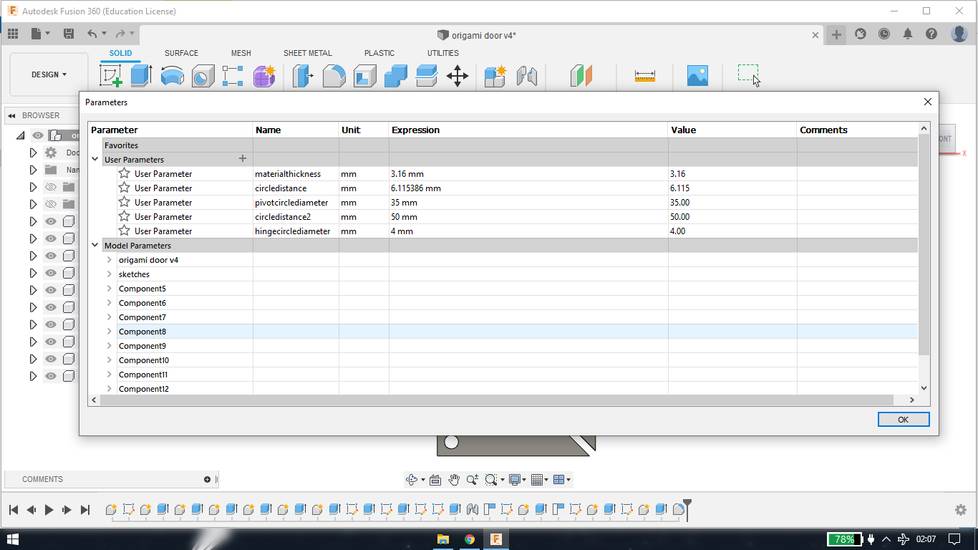
i then designed the hinges and pivot joint
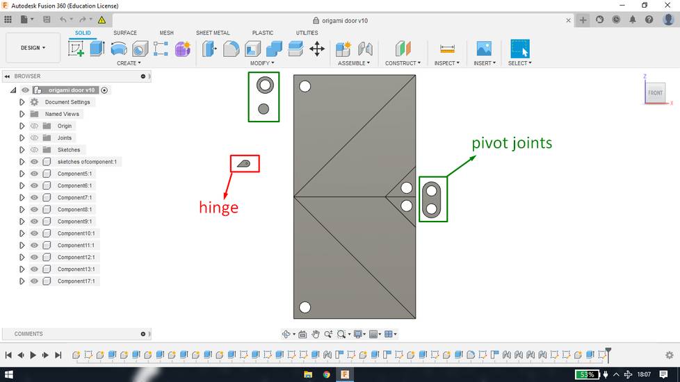
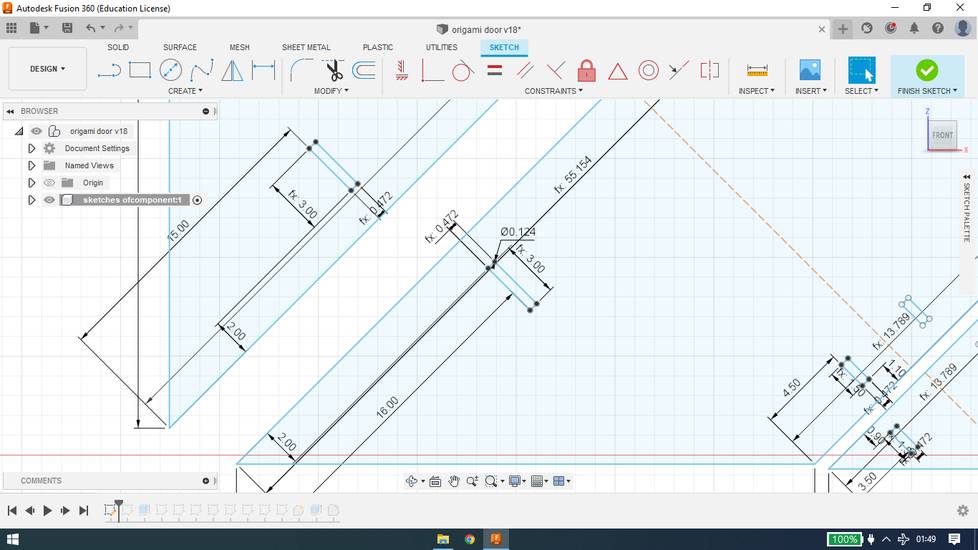
here is the parameters i used at that time,
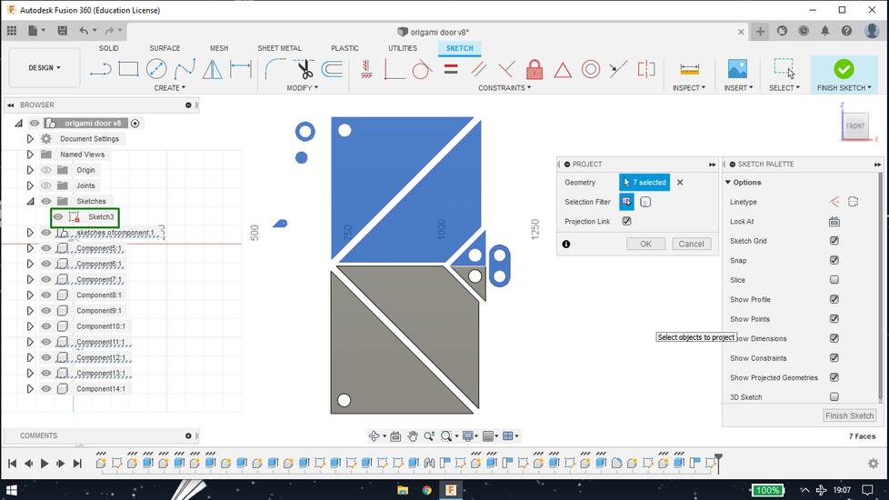
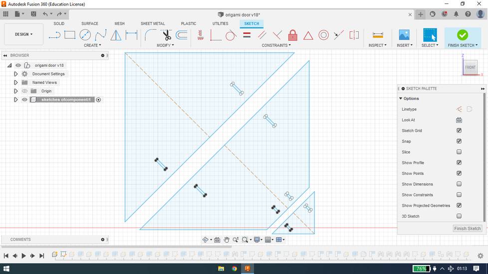
I then exported parts of the door as DXF fie. You can do that using project feature. Create a sketch and press "P" on your keyboard and select
all the parts you want to export as DXF. Then Exit the sketch mode and right click on the sketch you just created and select "Export as DXF"
Cutting and assembling the origami door (cardboard)
with the help of RDWorks software, i generated the toolpath to cut all the required number of pieces and i cut all that pieces into the laser
cutting machine, onto the cardboard
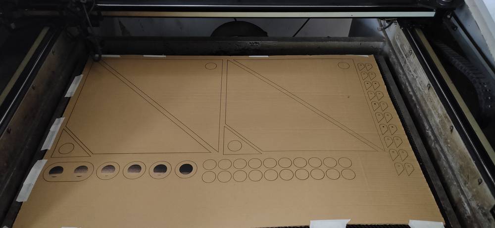
I miscalculated the number of pieces required. The circle with black patch in the middle(it was scanned) was two pieces short. So i cut them
later.
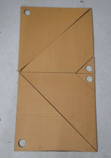
this was the door without hinges and pivot joints,
this is how i made hinges,
since the thickness of the corrugated sheet was 3mm, i stick two hinges together. For the cardboard pieces to rotate onto the single axis i used
chopsticks(3mm wooden sticks). To preven the cardboard pieces from sliding off, i used a stopper on both ends(dimension of stopper 12mm*2mm
concentric circles)
I then stuck 4 pair of hings on the front of the door,
I then stuck 4 pair pair of hinges on the back of the door. Because of the lack of space, i didn't stuck two cardboard pieces,
it turned out that the alignment of two hinges was not parallel so i was having difficulty in closing that part of the door,
i had to remove those hinges and stuck it again. The alignment and position of hinges is the key behind the smooth working of this door. Note
to self, make something in design so that i don't need to calculate/draw while attaching the hinges.
to make the pivot joints, i stuck the small diamaeter circle onto the big diameter circle,
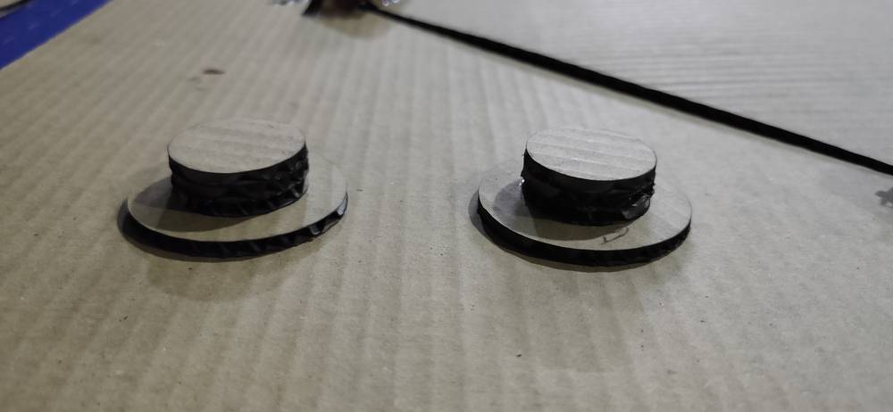
slide that into the pivot point of the door and lock it by sticking same other big diameter circle on the opposite end.
The door will now rotate around the pivot points with the help of hinges,
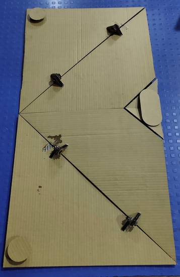
Here is how the door turned out,
You can download the design file and dxf files for the origami door(cardboard) from here:
DXF file for door parts
design file
Designing the origami door (plywood)
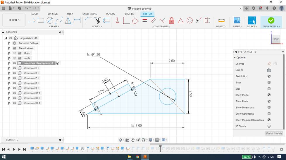
When the door i made was properly working as it should, i decided to scale up the design and make some changes so that i can cut the door onto
plywood.
I first scaled up the door from 15inch x 30inch(width x height) to 39inch x 78inch (width x height). Fortunately, the place where i was planning
to install the door had the frame size with 1:2 ratio(39inch x 78inch).
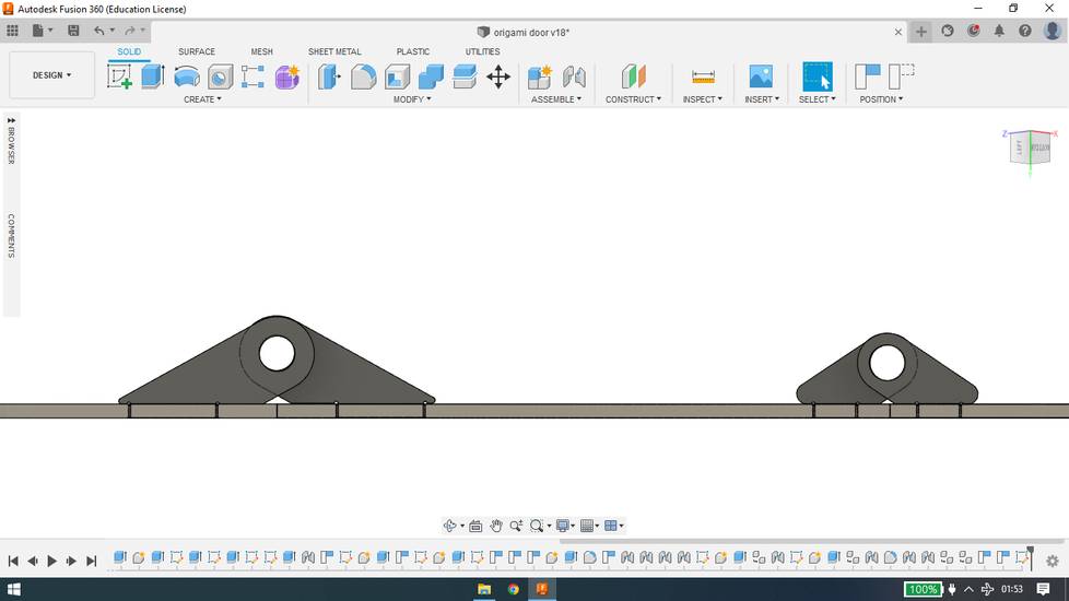
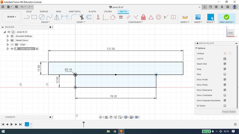
designed hinges, 5 inch one for small triangle,
designed hinges, 7 inch one for large triangle,
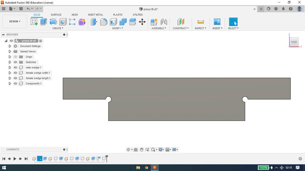
gave provision for hinges on the door,
the logic behind the dimensions of hinges and its provision on the door was to have the hinges in alignment,
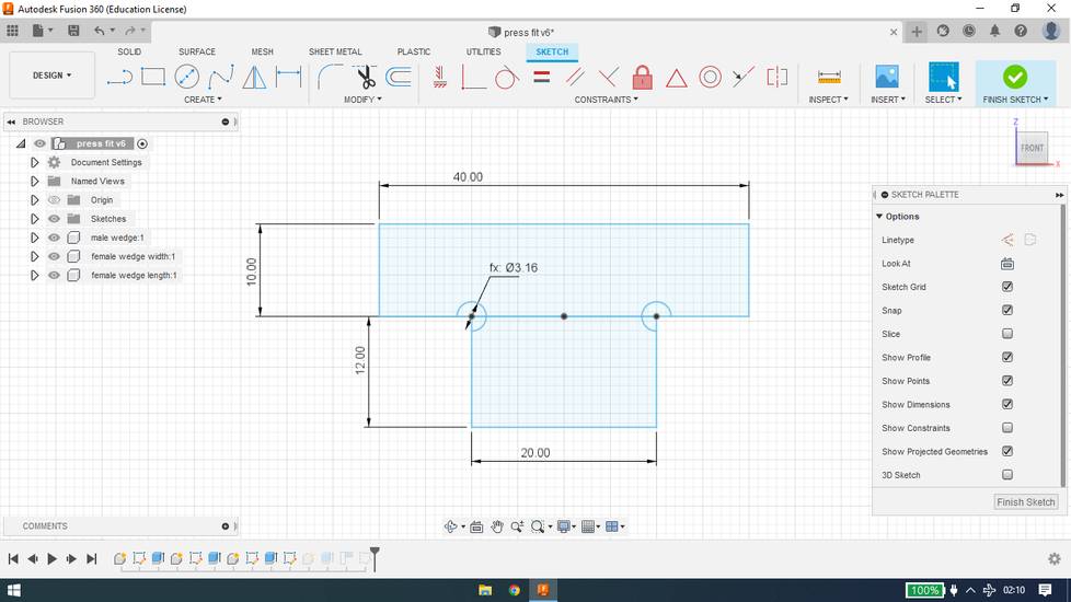
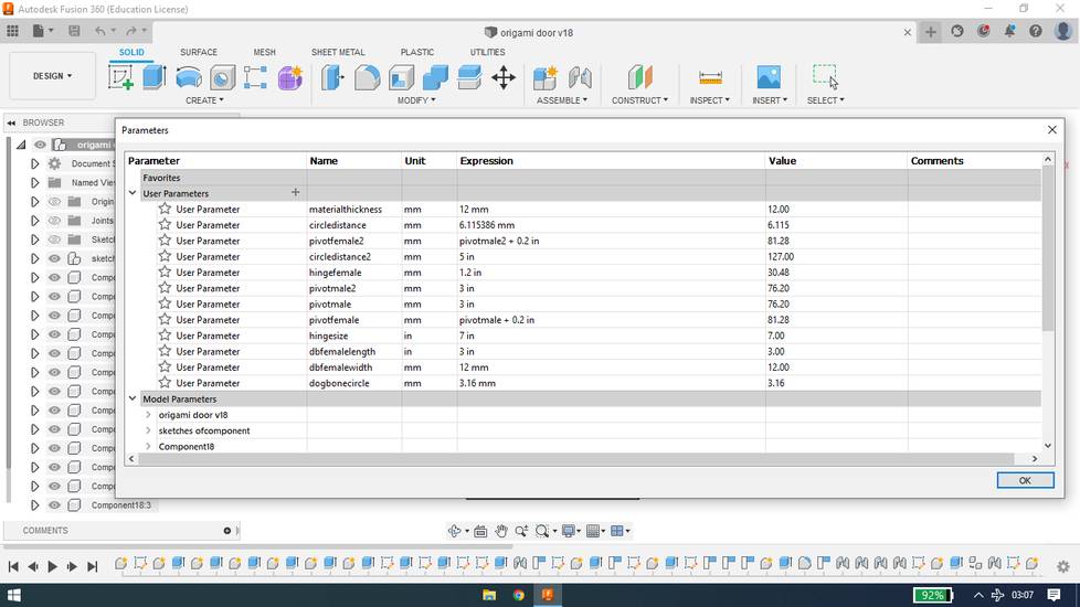
the reason behind i set the dogbone circle's diameter to 3.16mm is that the dimension of the endmill i was going to use to cut the plywood was
3.16mm.
To avoid any confusion, i am naming hinges as male hinge and provision for hinge on door as female hinge.
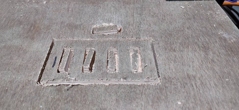
I got the dimensions of female hinge after doing test cuts for press fit. Here is how made the design for test cut,
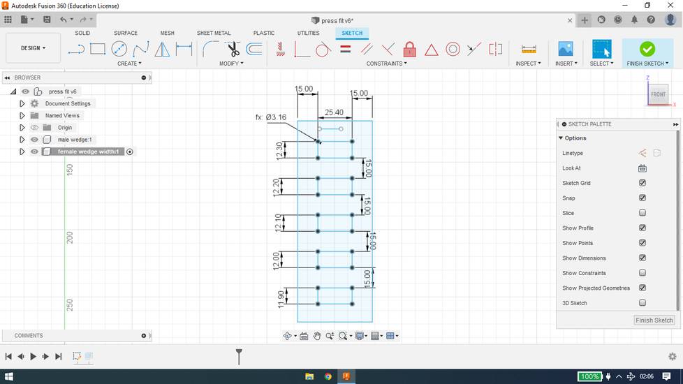
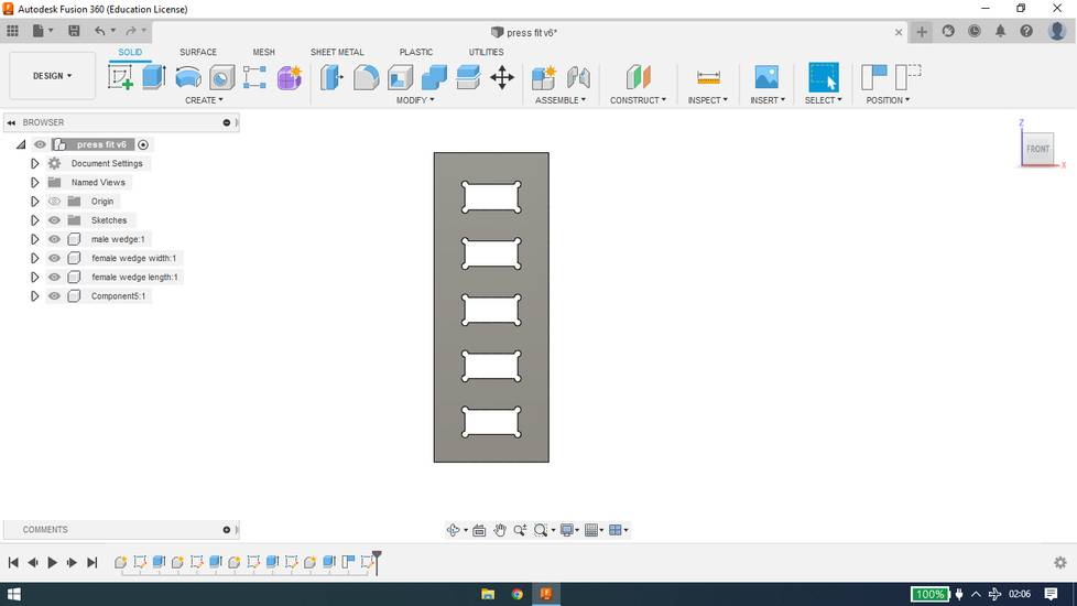
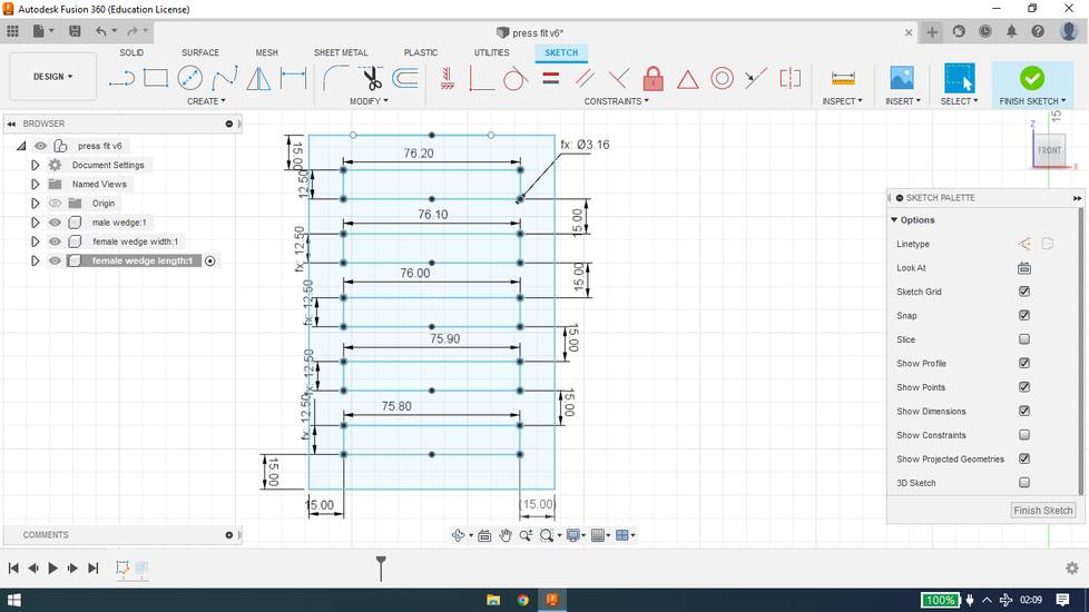
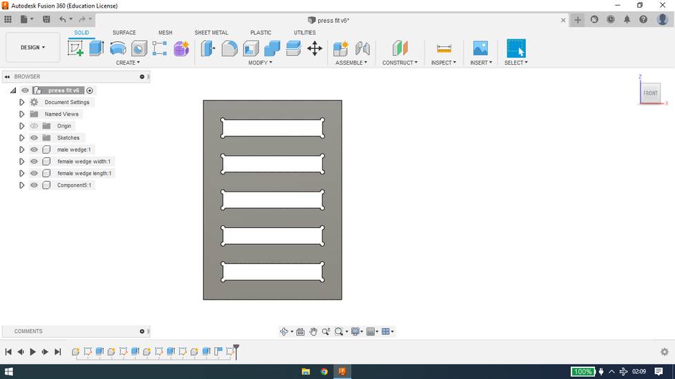
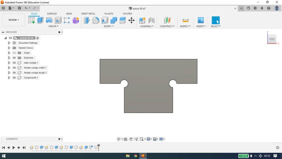
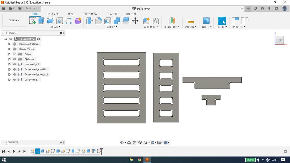
After cutting the test cut onto plywwod i checked allthe slots to see which male to female hinge ratio is better for press fit,
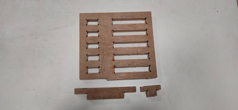
and it was concluded,
to keep the length of male hinge to 1.5inch(5inch hinge) and 3 inch(7inch hinge).
keep the length of female hinge to 1.5inch(5inch hinge) and 3 inch(7inch hinge).
keep the width of female hinge to 0.472inch(12mm).
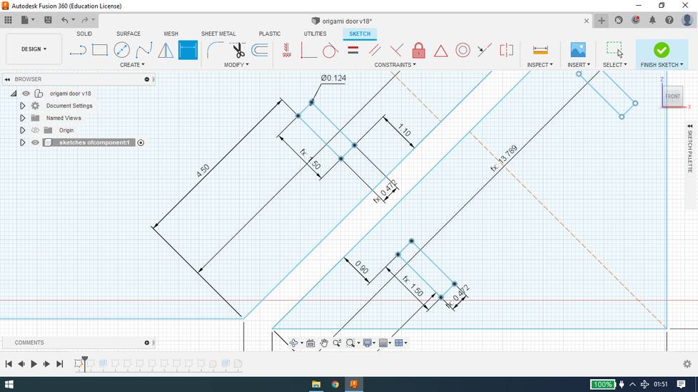
Here is how my parameters look like,
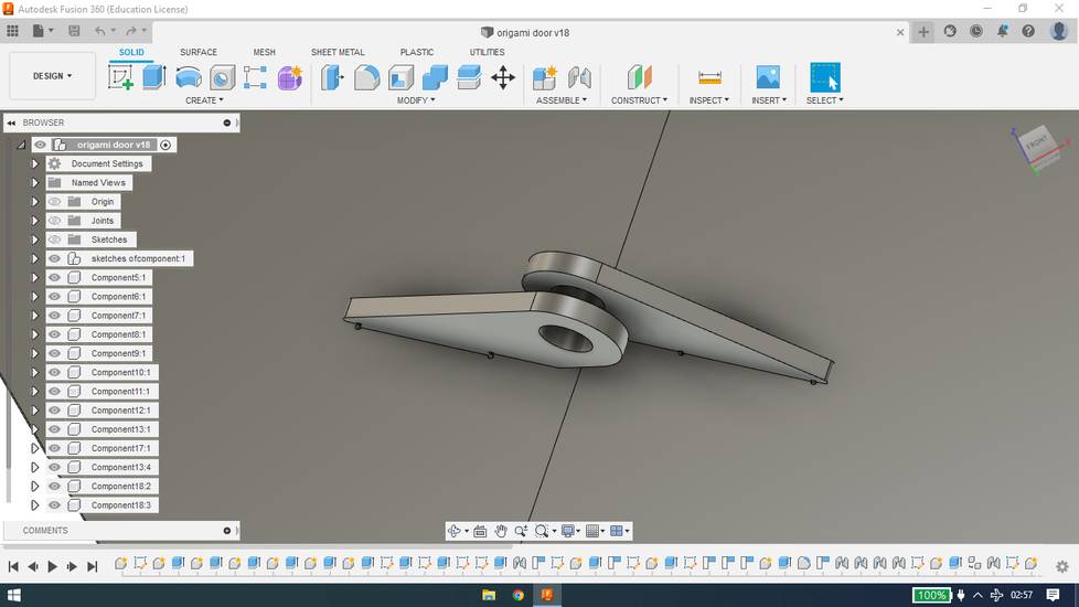
after the design was ready with partial(yet enough to confirm the design is fine) assembly,
I selected the necessary parts and with the help of "Project" feature in fusion, i exported the design as DXF, 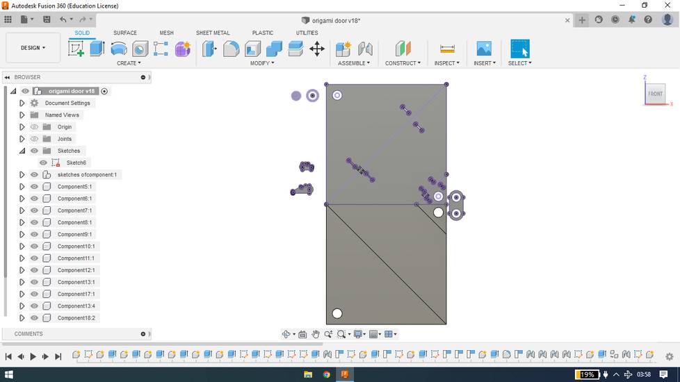
You can download the design file and dxf files for the origami door(plywood) from here:
DXF file for door parts (plywood)
origami door plywood(fusion)
You can download the design file and dxf files for the press fit from here:
press fit dxf
press fit fusion
Generating the toolpath
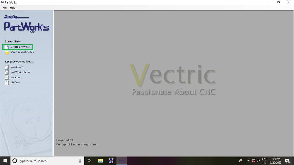
I was using Shopbot PartWorks software, which was pre-installed in College of Engineering Pune's(COEP) lab. While generating the toolpath you can
create three kind of profile: inner, outer and pocket.
In inner profile, the machine cuts the inside edge of the design,
one usually generates the inner profile for the part which are inside the deisgn.
In outer profile, the machine cuts the outside edge of the design,
one usually generates the outer profile for the outer edge of the design.
In my case, i had to use all three profiles. Here is the step by step description about how i generated toolpath for the door,
Click on "create a new file",
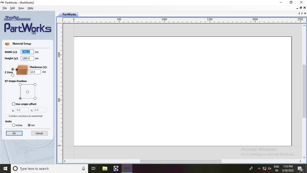
Under "Material stup" i selected units as mm and set the width, height and thickness as the dimension of the plywood i was using, 8x4 feet(2400x1200mm)
and 12mm.
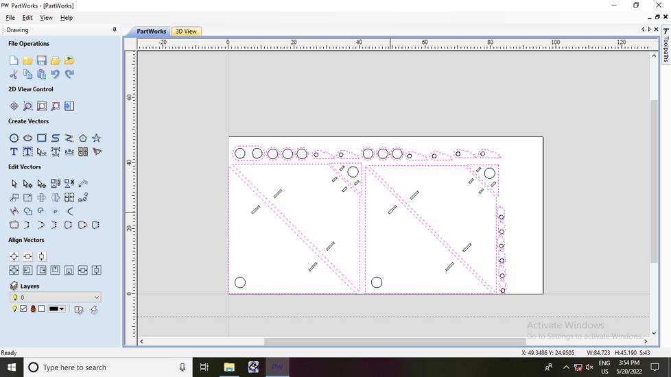
click on file and then import file. Select the DXF file you generated from the design,
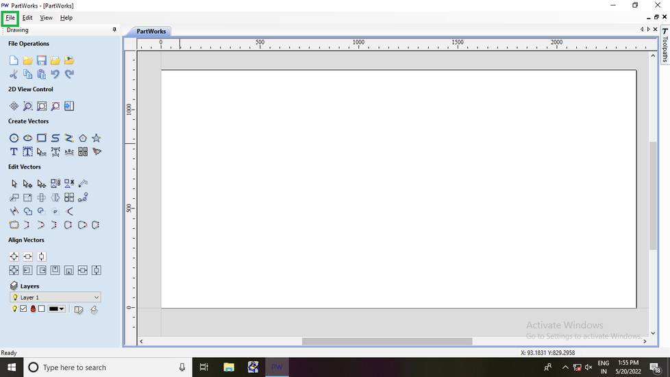
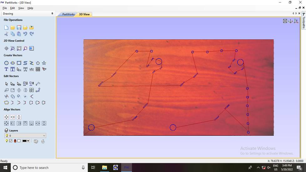
When i imported the DXF fie, the design looked very small on the canvas,
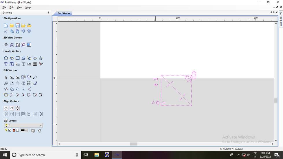
I then realised tha the design i made was partly in inches so for the Material setup i set the parameters with inche,
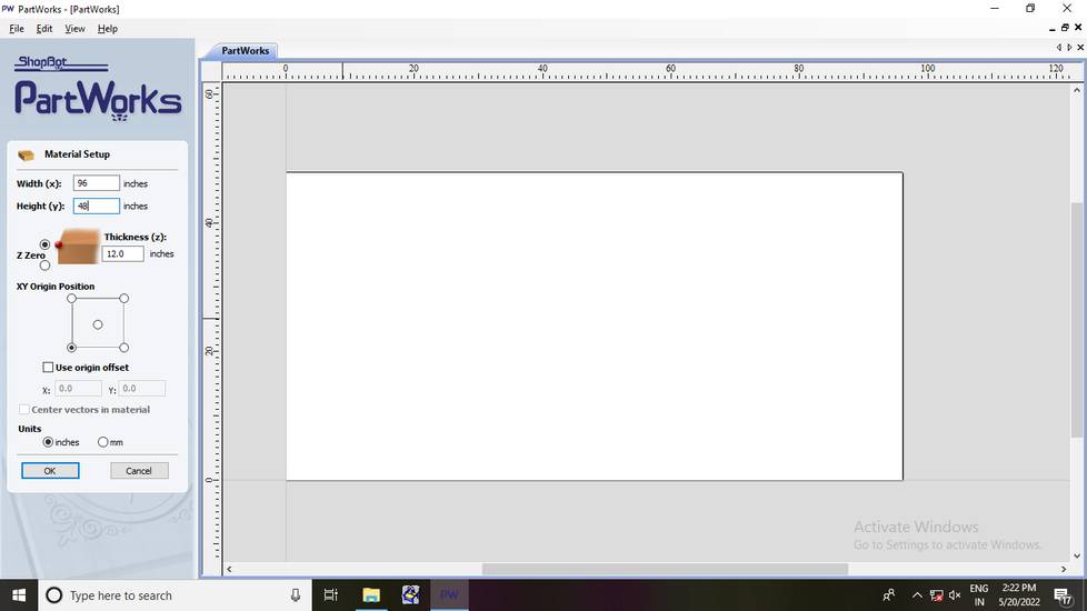
At the time of documenting i realised that i accidentally left the thickness as 12 inches but i didn't faced any issue, so i guess it is fine
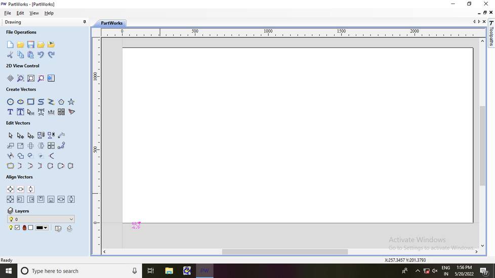
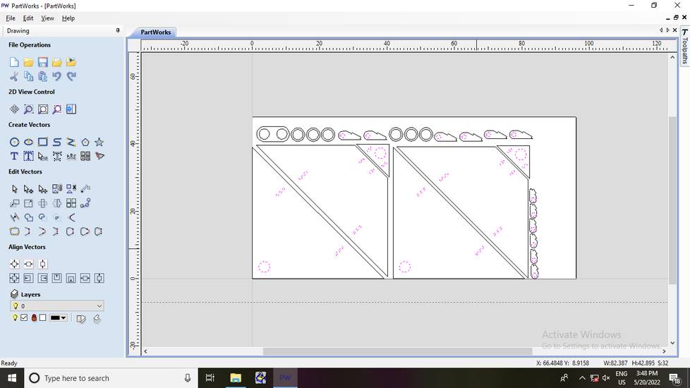
importing the DXF file after changing the Material setup to inches,
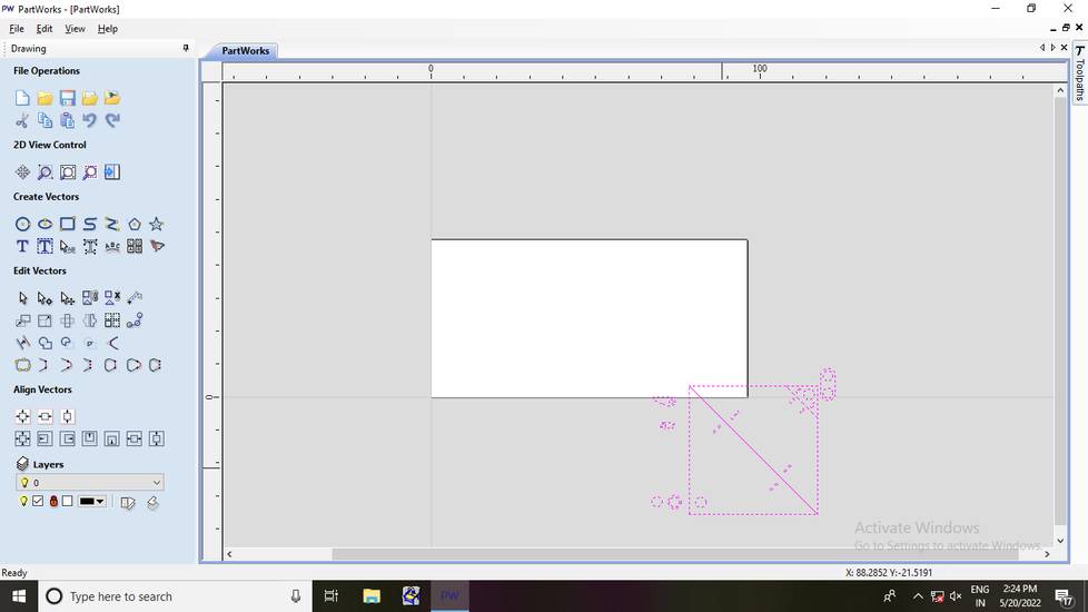
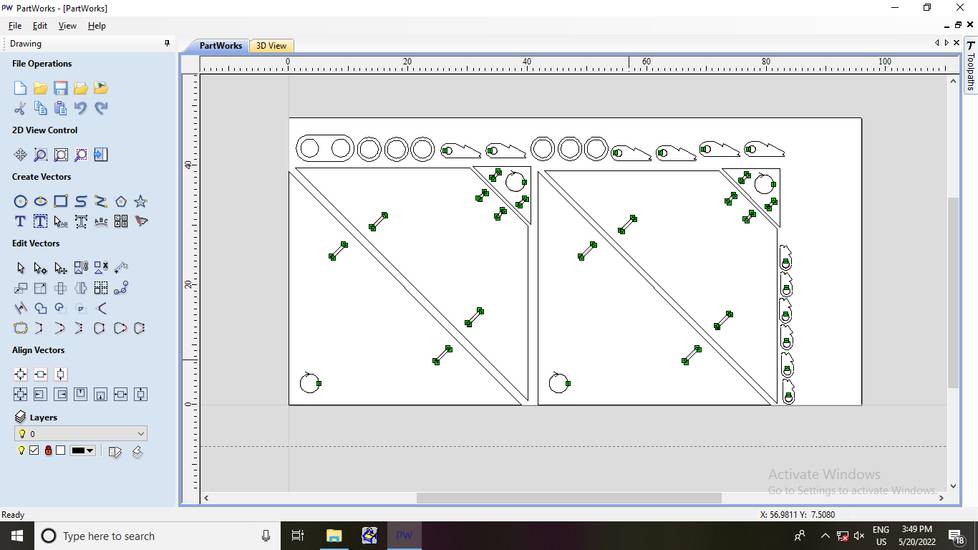
I copy-pasted few parts and then arranged the parts in the canvas. There was already some test design cut on one end of plywood so i wasn't
able to cut all the parts in one round, so i cut two 5 inch hinges and two 7 inch hinges in the second round, on the same plywood sheet,
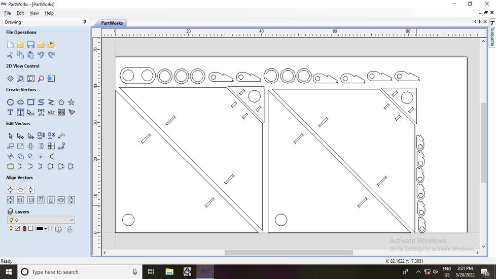
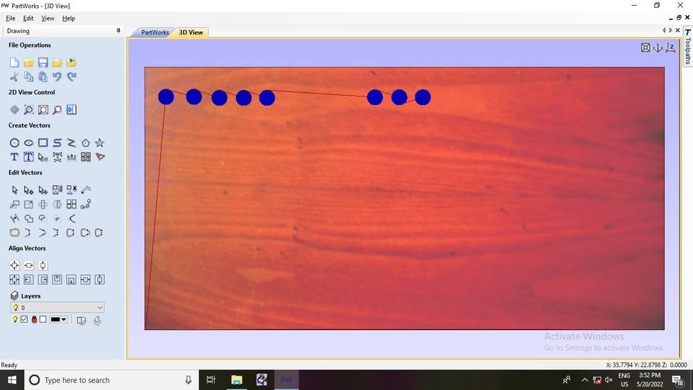
Note that while arranging the parts in canvas, always position the parts closest to the origin,
or else machine will go to the position where the part is placed and will start to cut the design there. PartWorks is completely opposite of
RDworks, Partworks won't only consider the design but will also consider the canvas and where you have placed the part to cut.
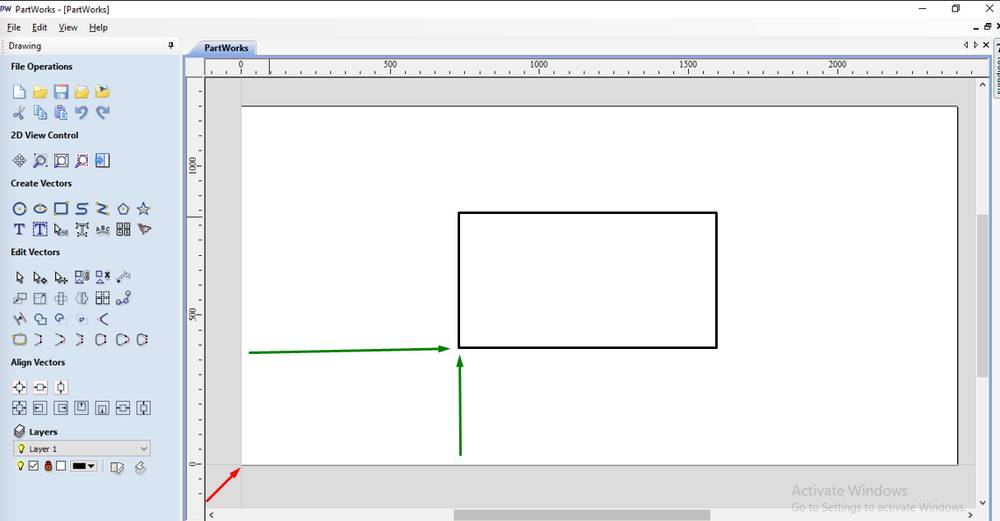
The red arrow pointed is the origin,
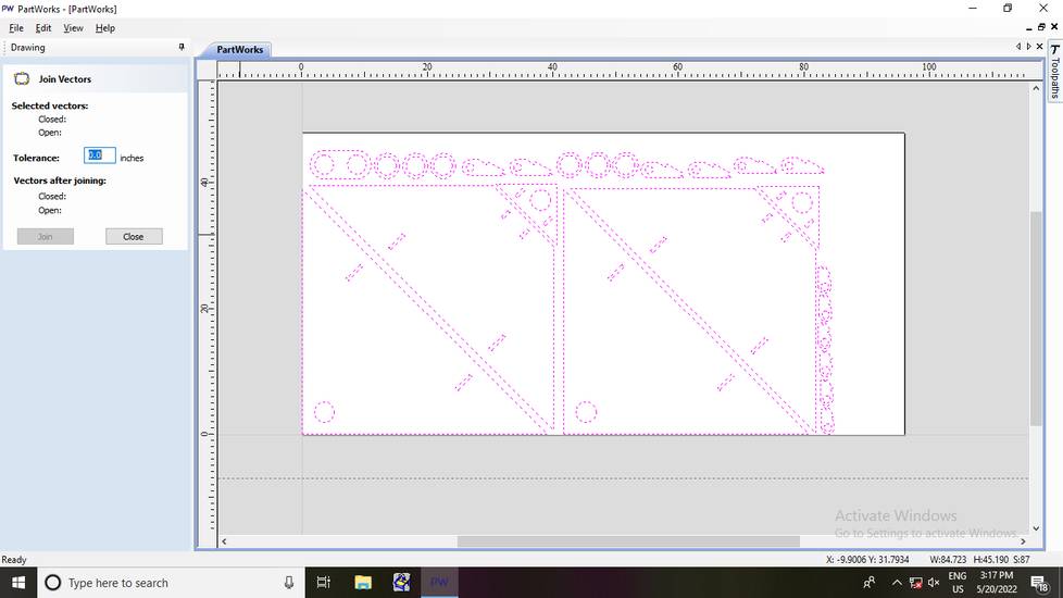
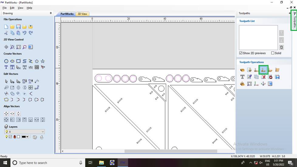
select all the parts on the canvas and click on "Join open vector"
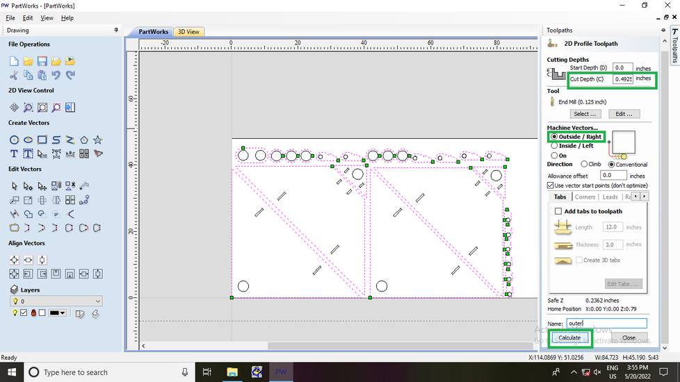
Select all the parts which you want to cut with inner cut then go to "Toolpaths" and click on "Create profile toolpath"
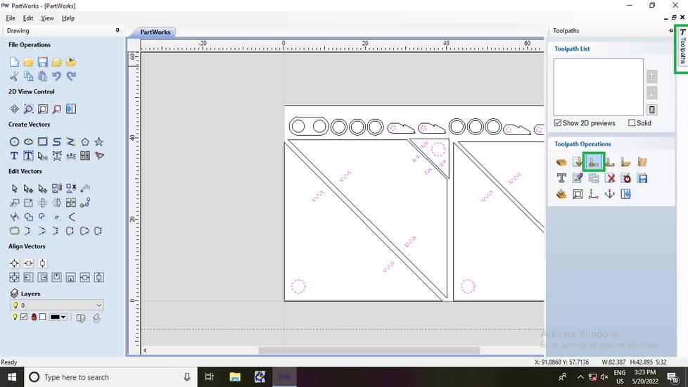
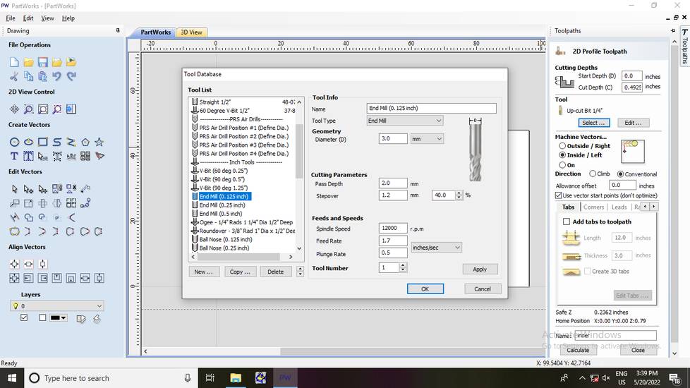
Click on "Select" under tools and select "End mill (0.125 inch)" as the tool,
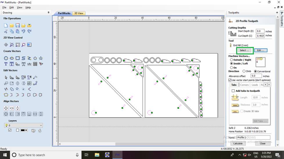
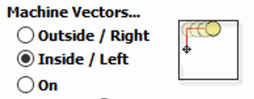
In the profile toolpath, I set the cut depth as 0.4925 inch(12.5mm), selected inside as Machine vectors and then gave the name and hit calculate,
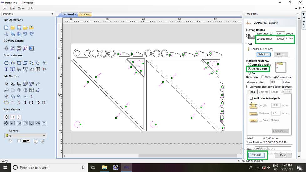
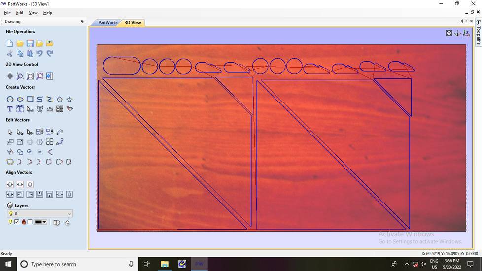
You can see the preview here,
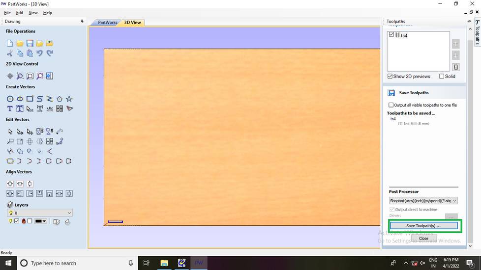
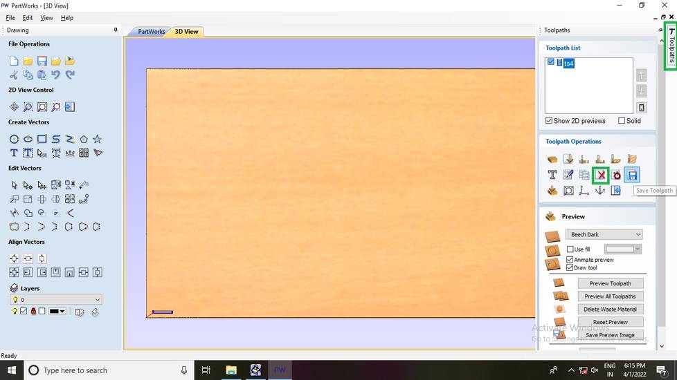
After the toolpath is generated, click on the "toolpaths" button again and click on "save" icon and then with your inner profile selected, click
on "Save toolpath",

After the toolpath is saved, go to the "Toolpaths" button and delete the inner profile,
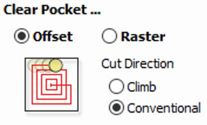
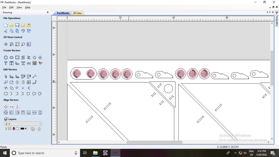
After the toolpath for inner cut was saved, i generated the toolpath for pocket. Select all the parts you want to cut with pocket then
Click on "Create pocket toolpath" button under toolpaths tab,
apart from the cut depth which i set to 0.079 inch(2mm) i kept the rest of the settings as it is,
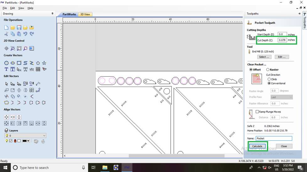
The preview for pocket toolpath,
Repeat the steps of saving the toolpath and deleting the profile from Toolpaths tab, just like i mentioned above.
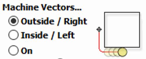
after the pocket toolpath was saved, click on all the parts you want to cut as outer cut and then go to Toolpaths > Create profile toolpath.
I set the cut depth to 0.4925 inch (12.5mm) and select outside as machine vectors and clicked on calculate,
i was getting the message saying "24 open vector",
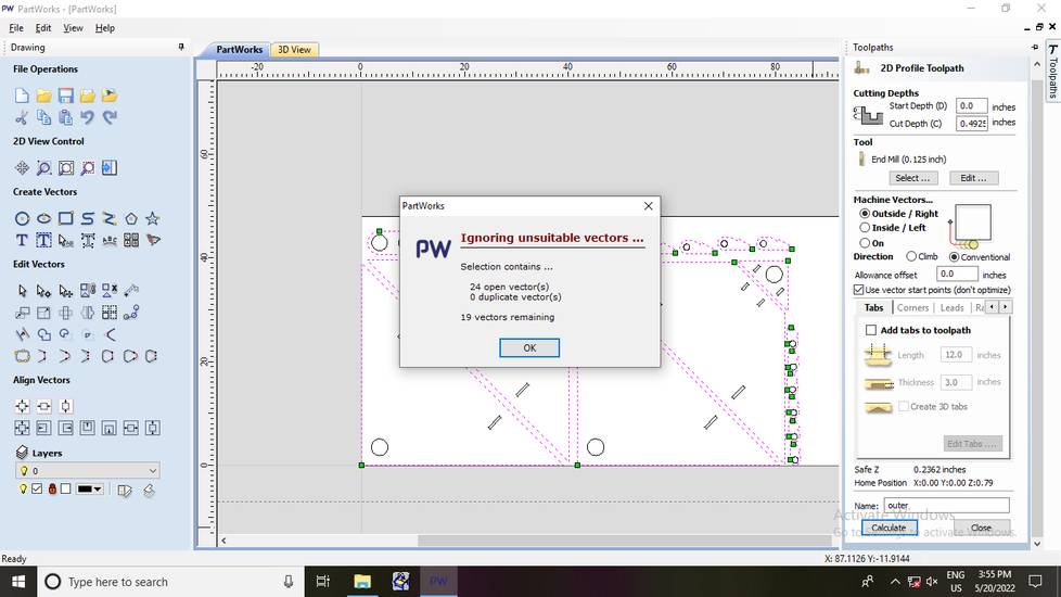
I clicked on okay and there was nothing wrong with the preview,
I then join the vectors with 0.0001 inch(earlier it was 0) and re-generated all the toolpaths again,

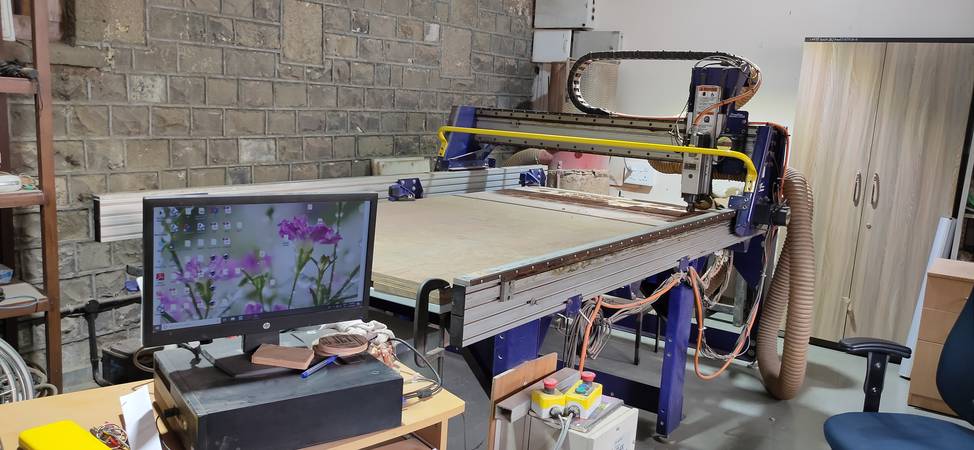
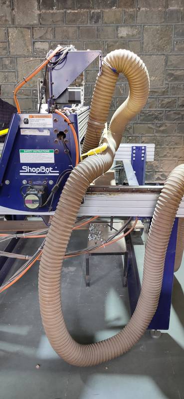
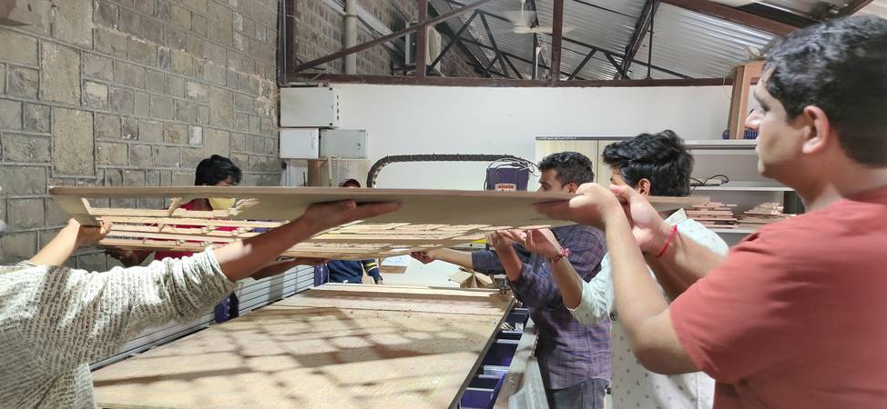
Onto the machine
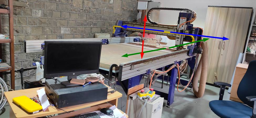
Here are some heroshots of the machine,
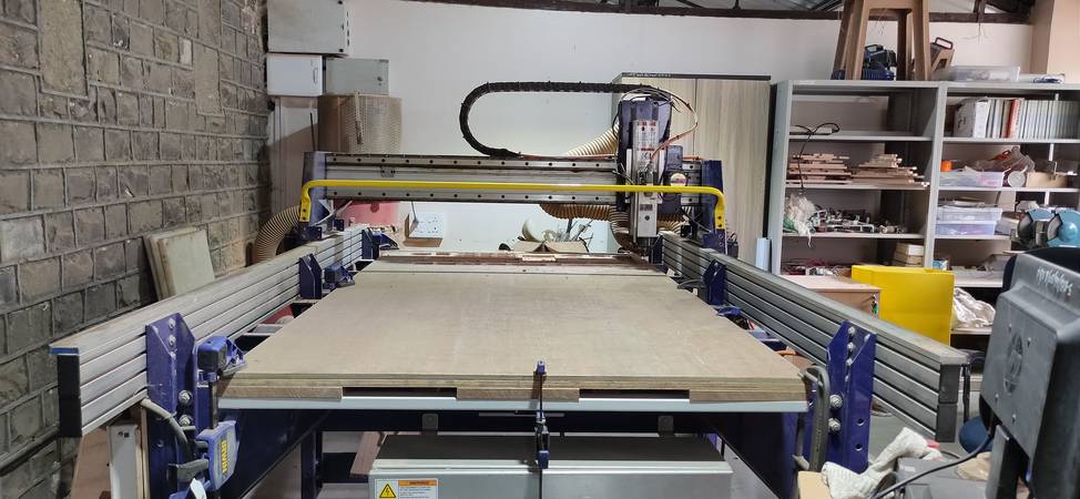
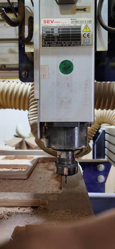
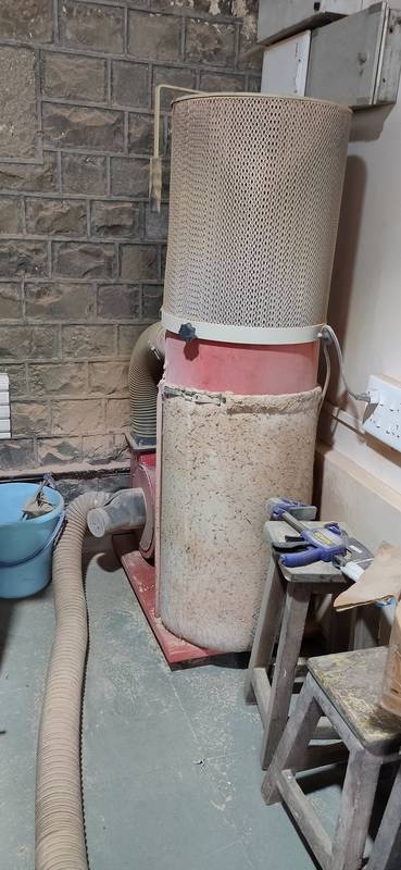
The pipe connected near the spindle is for collecting the dust and debris comming from the plywood while cutting. The the dust and debris
is sucked through the pipe and goes straight to the dust collector,
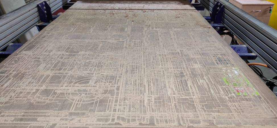
just like any other routing machine, the shopbot too has a sacrificial layer on the bed,
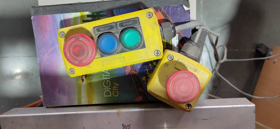
These are the remote start(green), reset(blue) and stop(red) button. You turn the spindle on and off using the start and stop button. You reset the
previous origin using reset button. You are sometimes instructed by the shopbot software to press the reset button,
You control the movement of the spindle using the four arrow keys and the Page up-Page down key. You move the spindle on the X-axis(green)
using left-right arrow key. You move the spindle on the Y-sxis(blue) using up-downn arrow key. You move the spindle on the Z-sxis(red) using
page up-page down key,
For the group assignment, we had to do the lab's safety training. So apart from learning about how to operate the machine, here is all the things
we did for the group assignment,
Loaded the sheet to do the test cuts,
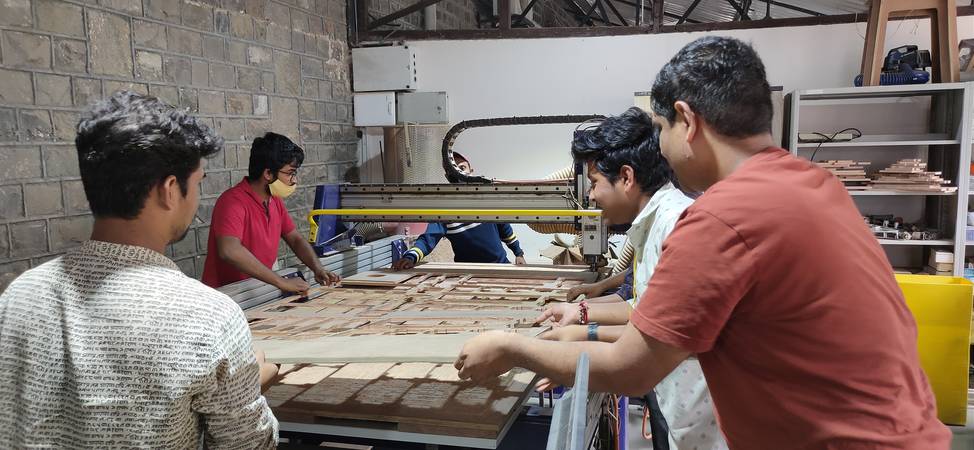
fixed the plywood onto the bed using multiple clamps,
made a small degign for test cut and generated the toolpaths,
before we cut the design on the plywood, we were instructed when to use the remote start, stop and reset button(i'll explain this later) and
were advised to always be in the close vincinity to the remote buttons in case something goes wrong.
We were instructed to always switch on the dust collector machine before starting to cut the plywood. We were instructed to use the
saftey goggles and noise cancallation ear cups while operating the machine,
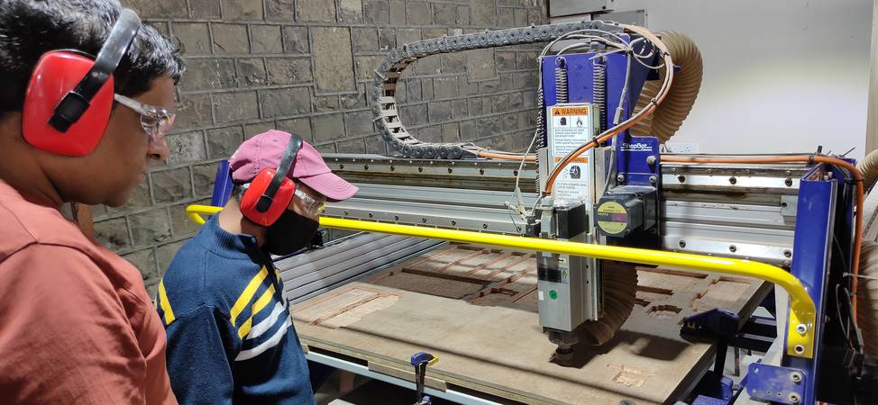
cutting the design on the plywood,
Link for group assignment page:
https://fabacademy.org/2022/labs/vigyanashram/groupassig/groupassignment5.html
With the toolpath file for inner, pocket and outer cut ready, it was time to cut the pieces into the CNC wood router machine, Shopbnot. The
toolpath file gemerated is in the form of SBP file. Here is how i cut the design onto the plywood using the toolpaths generated,
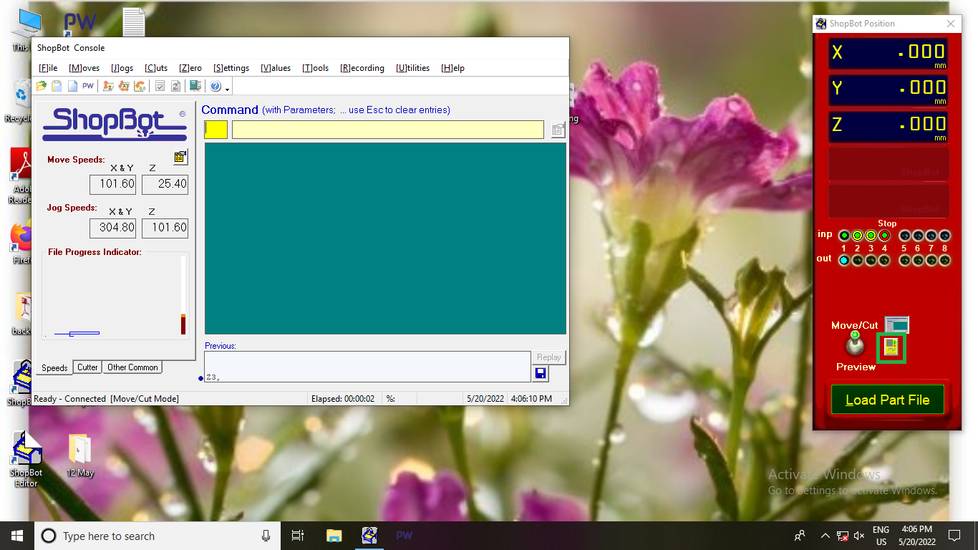
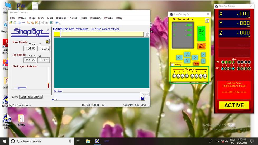
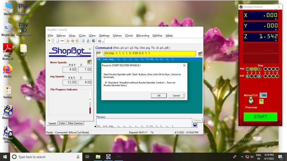
I was using the shopbot console(the 2D one) software which was pre-installed in the lab's PC. This is how the interface looks like,

When you open the software, you might get asked
to press the remote reset button, so press the reset button.
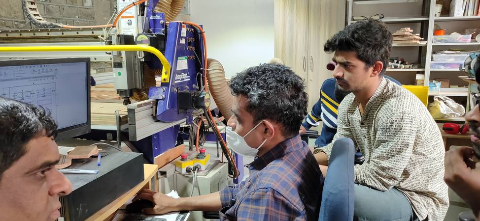
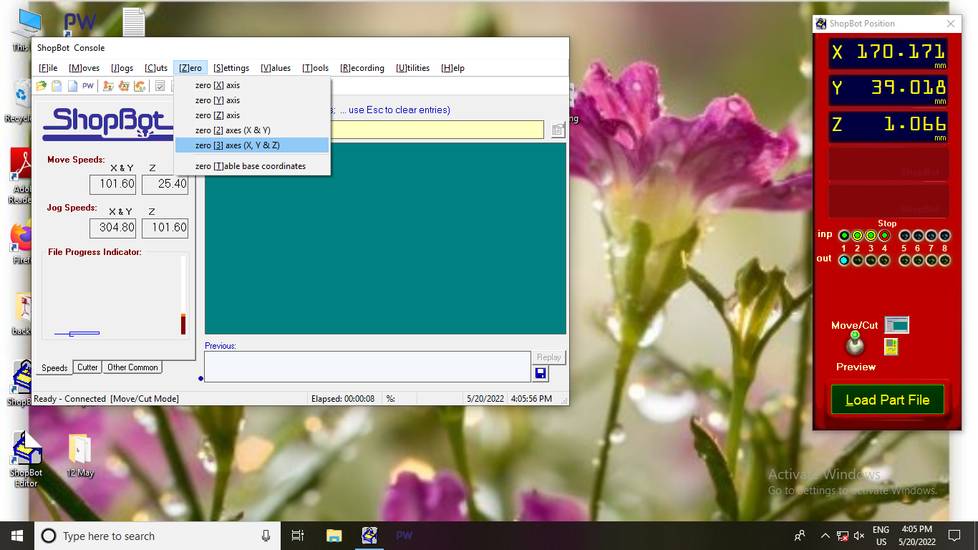
You first need to set the origin. To do that use the arrow keys and page up-down keys to move the position of the spindle. But before positioning
the spindle, click on the yellow box box in the console and make sure the lever number 1 and 4 us up,
You first need to set the X and Y axis of the spindle. Once the X and Y axis is set turn the spindle manually on by pressing the remote start button.
Once the spindle is on, bring the spindle down slowly. Keep bringing the spindle down until the endmill starts scratching the surface of
the plywood. Then click on "Zero" and select "zero [3] axes (X, Y & Z)". By doing this you set the origin of the machine and the spindle must
had stopped spinning, bring the spindle up then.
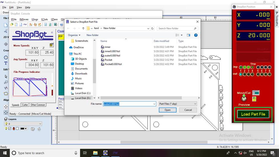
with the origin set, click on "Load Part File" button and select the file you want to cut. Always the inner/pocet parts first and then cut the
outer part at the last,
Once the toolpath is loaded click on the start button,
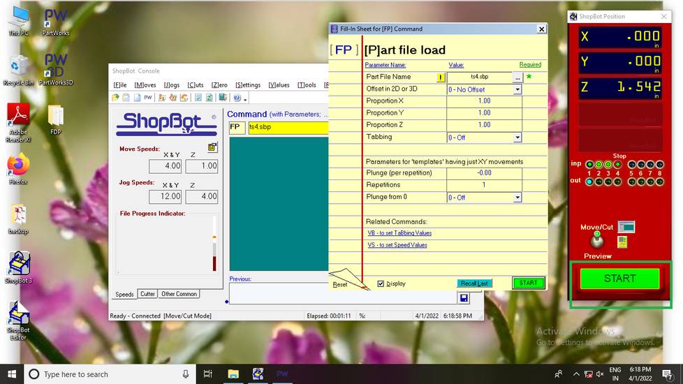
A menu will pop up asking you to press the remote start button. So press the remote start button and once the spindle starts to spin, click
on ok,
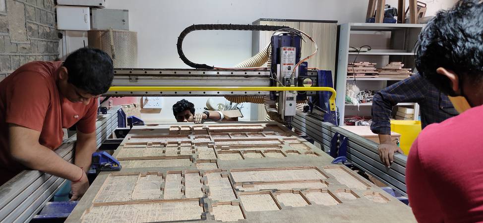
Here are some hero shots of the machine in action,
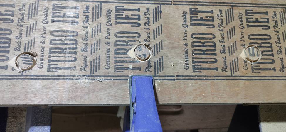
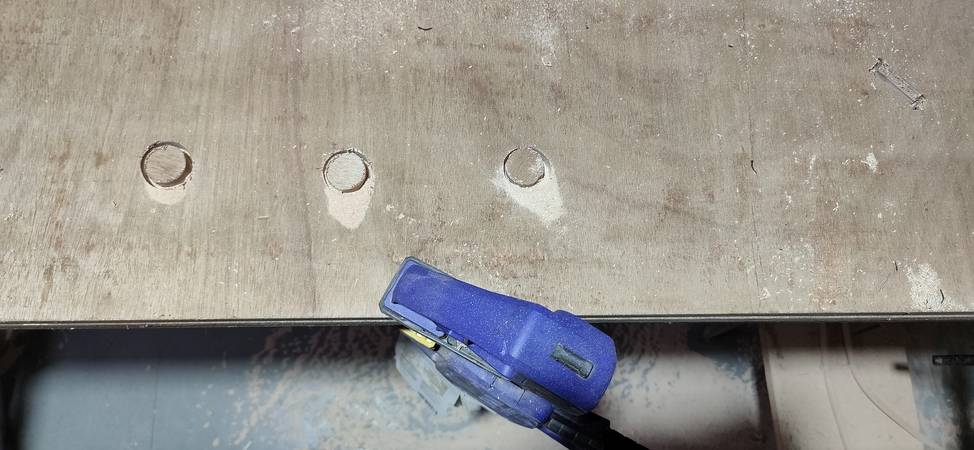
Inner cut,
just like i anticipated, the machine just plunged once to make the dogbone circles(i already got this result when i cut the test pieces for the
press fit).
Once the machine was done cutitng the inner cuts, i observed that the machine has cut some inner parts which was very close to the clamps. I thought
the spindle might collide with the clamps while doing the outer cuts so i shifted the clamps away(the image you'll see below is for the hinge
so after shifting the clamp, the clamp was posiitoned between two outer cuts of the hinge),
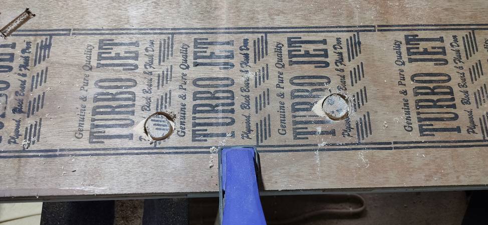
Pocket cut,
Before starting the outer cut i changed the alignment of the clamps for saftey,
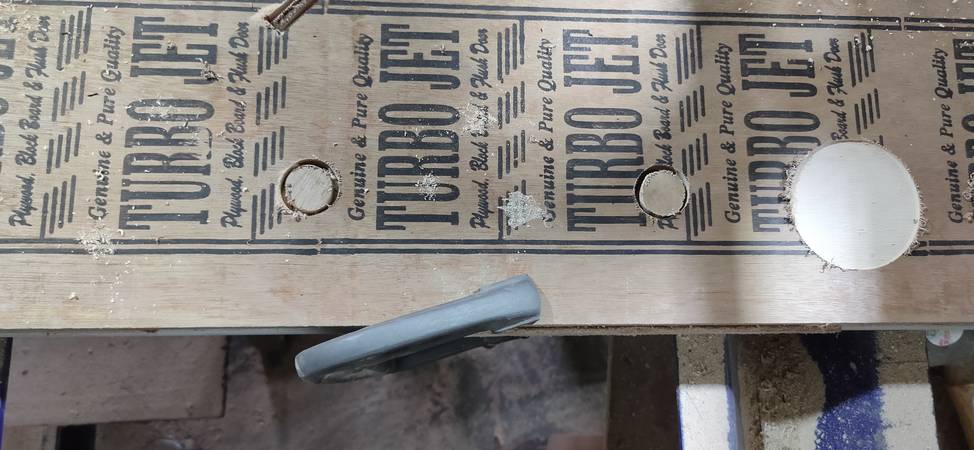
Outer cut,
While arranging the parts in PartWorks, i did cosider the size of the clamps but with the context to the endmill. What i should have done was
considerd the play area for the machine with the context of the spindle. The video you see above was a close call and i still change the alignment
of the clamp for safety, before the second pass.
Look at the posiiton of this part after being cut,
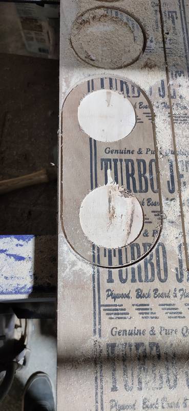
Because there were small parts like hinges, i had to press down the parts with a wooden stick during the last pass because the part
would shift from it's position and get crumpled with the endmill. I should have asked my instructor in charge a few more times for the nails
and used them to fix the parts,
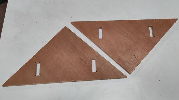
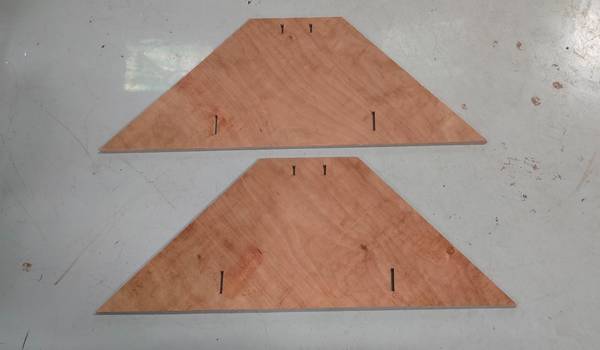
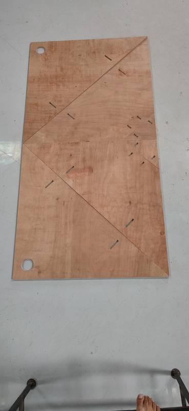
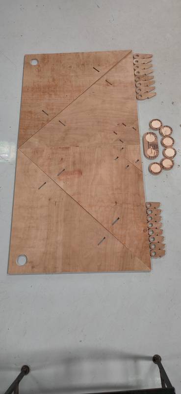
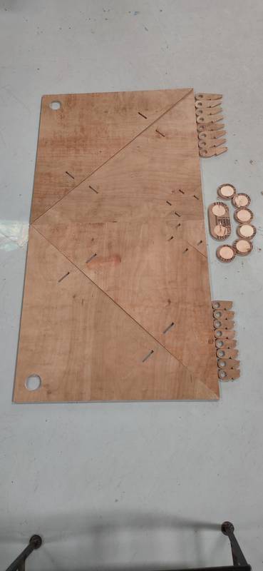
Here is the shot of finished job,
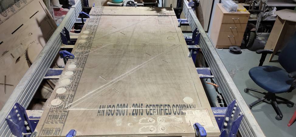
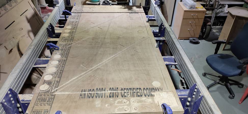
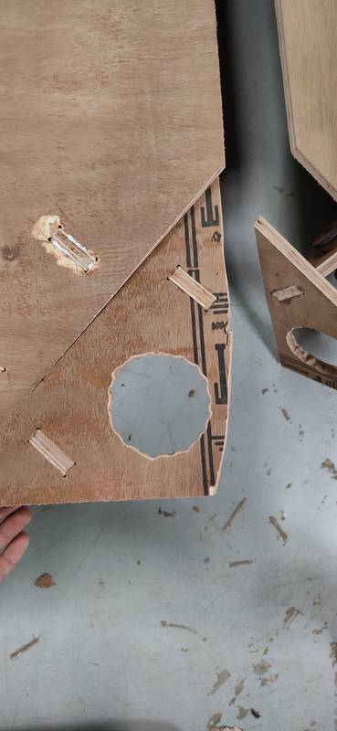
This is how the cut part looks like,
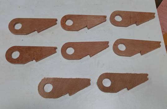
The machihe didn't cut the hole in the center, even though i selected that part while generating the toolpath,
Up till now, i had done the job of designing, cutting and assembling the origami door on cardboard to check it's functionality. I had also done
the job of modifying the design and cutting then in the CNC wood router machine. Now the remaining job was to make the cylindrical wooden rod
for the hinges and fitting the door onto the metal frame of the place where i had planned to install the door.
Attempt to make the cylindrical wooden rod
I wanted cylindrical blocks of wood with 1 inch and 3 inch diameter for hinges and pivot points. I looked for the wooden block on thr campus
and found few logs of wood. I then started to cut them in lengths so that i get log of wood which are somewhat straight and favourable for the
lathe machine.
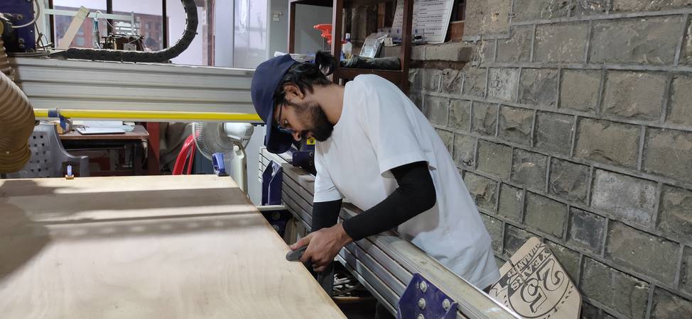
For cutting the logs of wood i used Power Hacksaw machine which was in the workshop. My colleague, Ghanshyam, helped me with cutting few logs
and taught me how to operate the machine,
The logs of wood,
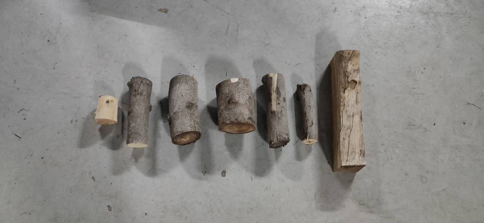
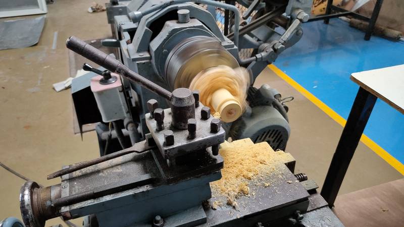
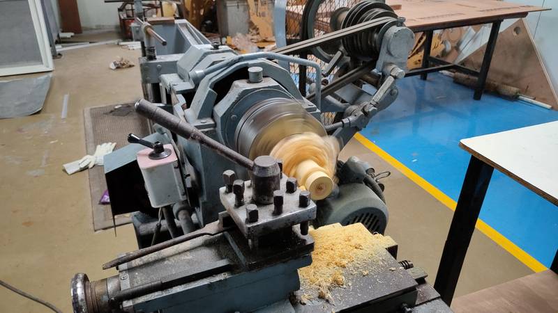
With the logs of wood ready we started to cut them into the lathe machine,
I did cut one side of the log down to 1 inch(it was about 2.75 inch diameter log) and the log was sliding in the hinges pretty fine,
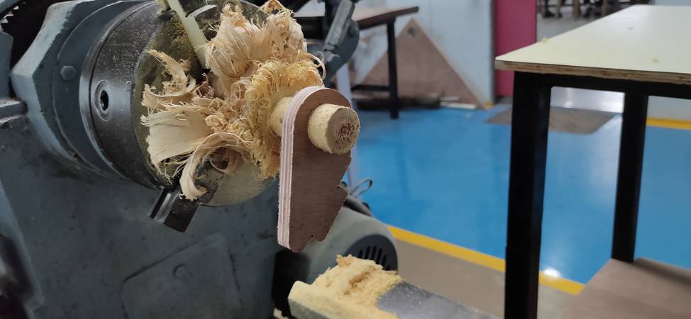
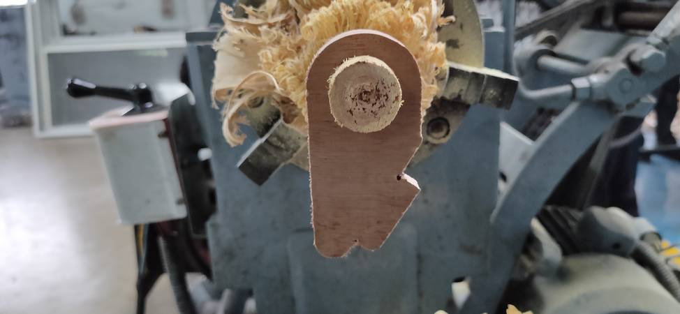
However it took me around 1 hour just to get single side of the log cut down to 1 inch. I had to cut total 12 pieces of log for all the hinges
and pivot points,
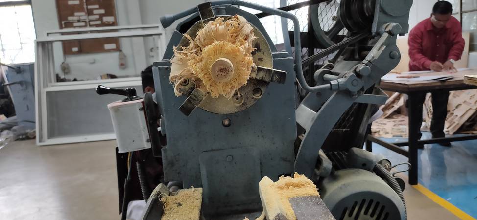
I did't anticipate that it would take this much of time to cut the logs on lathe. Also the wooden log i was using was small compare to the
other logs, so i didn't need any support from the other end of the lathe. I was cutting this wooden logs on June 28, 24 hours before the
local evaluation deadline, so i decided to skip the idea of cutting all the 12 logs into lathe and considered purchasing the logs from market
or to place
the order to someone who can give me logs of cylindrical wood with the dimensions provided. So i will continue to work on the door
once i get the cylindrical wooden logs for the hinges and pivot points.
Edit: 13th July, 2022
Assembly
After the local evaluation was done, i tried to search for some vendors in Pabal where i can get the cylindrical wooden logs. With no success in finding any vendor in Pabal i had to travel to Pune in search for the wooden logs. There is a timber market located in Bhavani Peth area in Pune where i found a carpenter with wood turning lathe machine. I gave him the order for wooden logs and provide him the dimensions and after a couple of minutes, my wooden logs were ready. Circumstances were such that i was not able to shoot any photo or video, but just to give you an idea about how wood turning lathe machine works, here is a youtube video for that,https://www.youtube.com/watch?v=JSEVwvrpewE
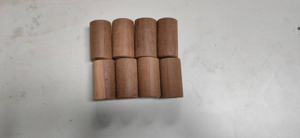
Here are the cylindrical wooden logs with 1 inch diameter and 2 inch length for hinges,
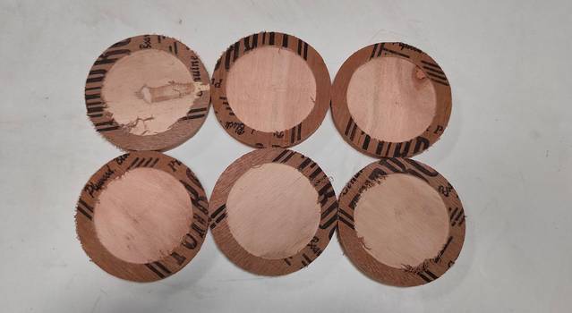
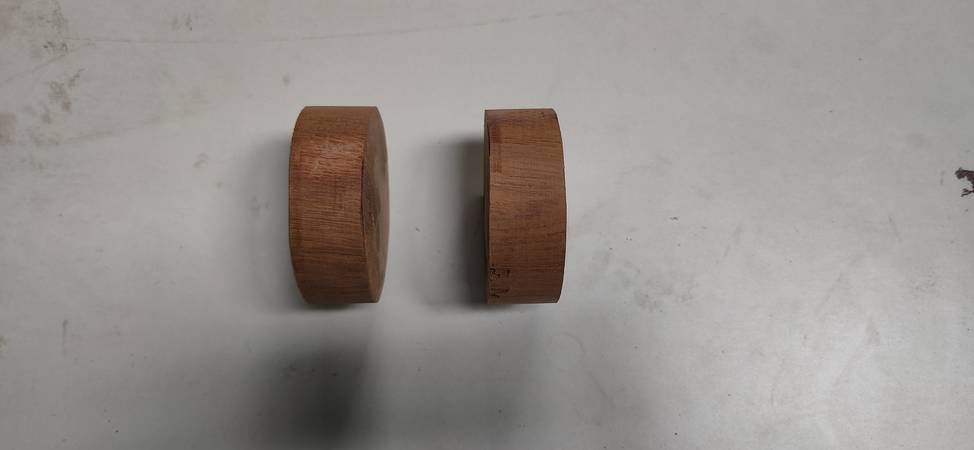
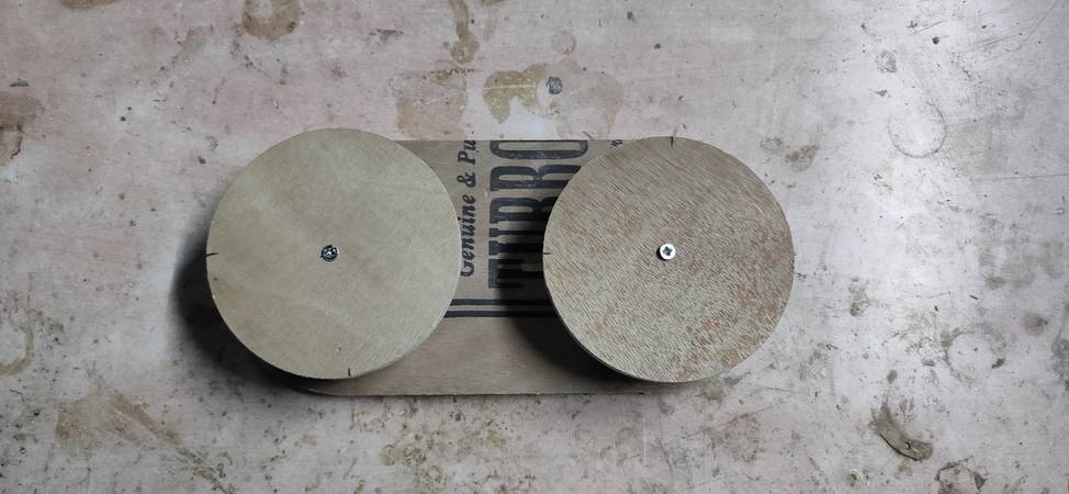
Here are the cylindrical wooden logs with 3 inch diameter and 1 inch length for pivot point(door handle),
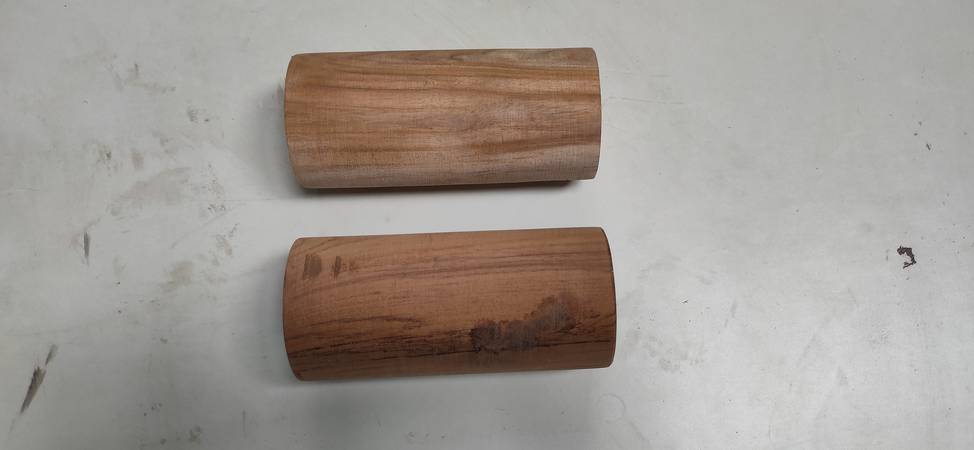
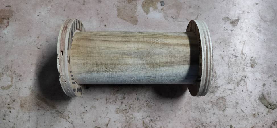
Here are the cylindrical wooden logs with 3 inch diameter and 6 inch length for pivot point(on which the door will be mounted),
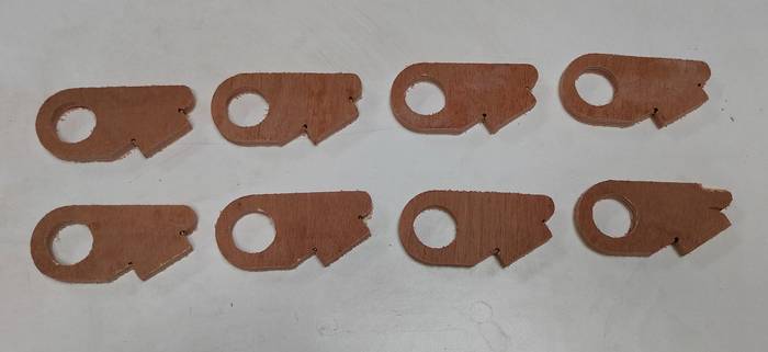
It was then that i realize that i forgot to cut the stopper for hinges in the shopbot machine. So i cut the stopper into the laser cutting machine with 6mm plywood sheet,
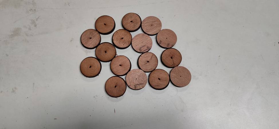
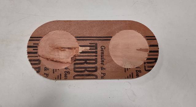
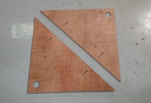
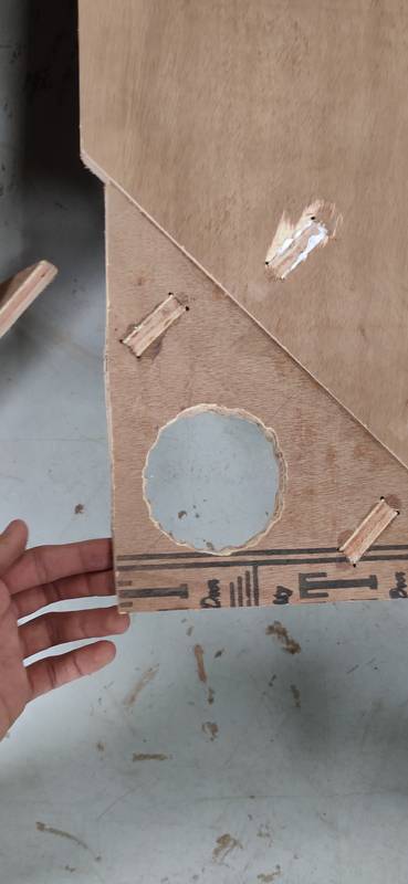
There was a piece in the design files with a 3 inch hole in the middle. Now at the time of generating the toolpath i did select the circle for cutting but still the machine didn't cut the hole,
We don't have the shopbot machine in the lab so for the assignment i had to visit COEP college in Pune. While i was there on the campus cutting the pieces onto the shopbot, i realised that the machine has not cut the holes in two pieces. I then generated the toolpath for the two pieces and tried to cut them again but due to some error "Parameter vakue below range for VS" i was not able to cut the pieces that day. I talked to the instructor in charge of the machine, Ms. Apeksha, regarding the error and after getting assurance that she'll help me with cutting those 2 pieces, i travelled back to Pabal. After waiting for 5 weeks, i still didn't got any help from their side so with no option left i had to work out with the 2 pieces that i had.
So i drilled multiple holes in the circular pattern(taking measuremenmt of 3 inch circle) and cut the wood in between the hole with the help of hacksaw and smoothen the inside surface with sand paper,
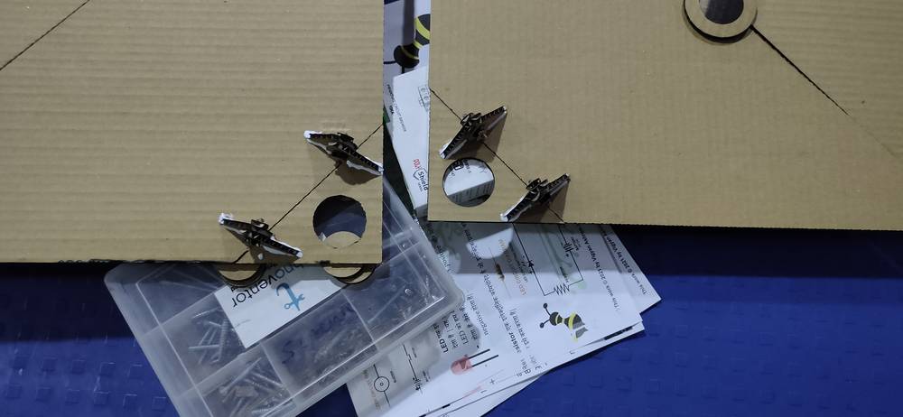
with all the parts of the door ready, i started the assembly. I started with atatching the hinges. I used glue for better adhesion, though even without the glue, the grip was strong but i didn't want to take any chances,
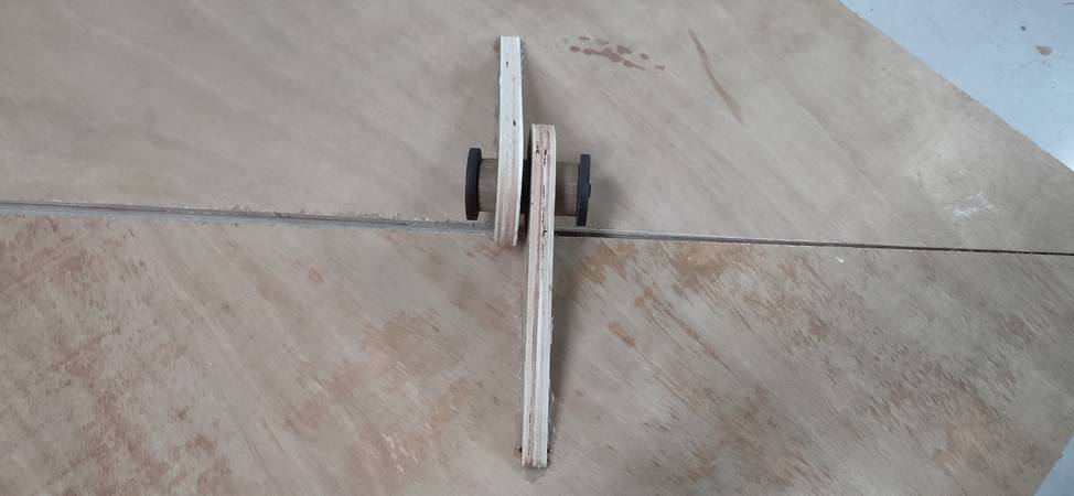
with the hinges attached, i started to insert the cylindrical wooden logs into the hinges and pivot points and locking the cylindrical wooden log from slipping by attacing the stopper on both ends,
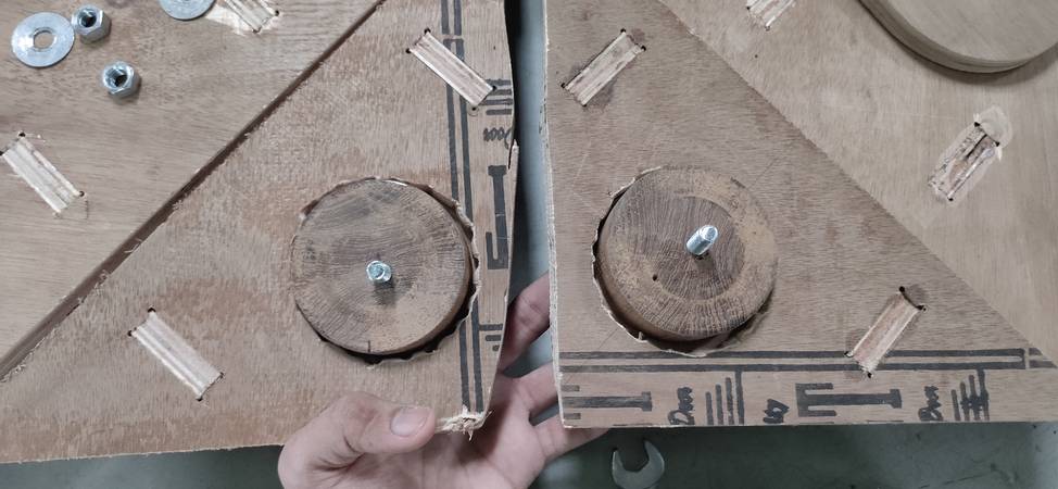
atatching the stopper onto the cylindrical wooden log was not that simple like put the stopper onto the wooden log and screw them together. I had to first drill hole in the wooden log as well as the stopper and then screw them together,
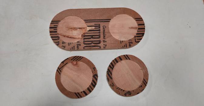
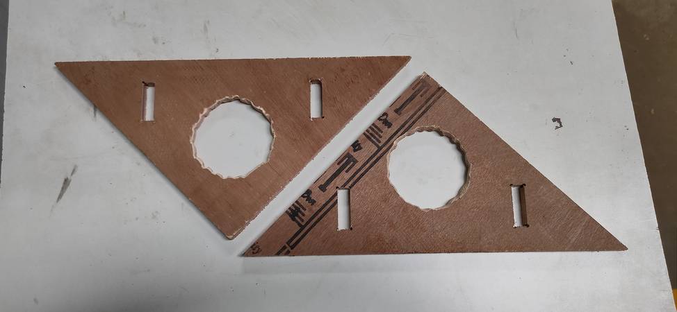
while screwing stopper i should have designed and cut a piece of MDF/Plywood with the same diameter as the cylindrical log and a hole in the centre so that i didn't had to measure the centre of the log or tentatively drill the hole in the centre which resulted into hole being offset to the centre.
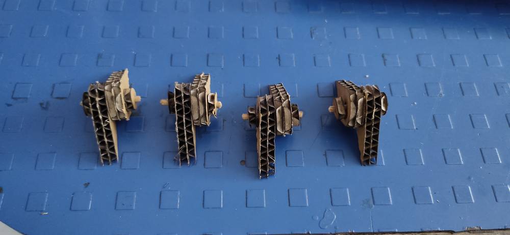
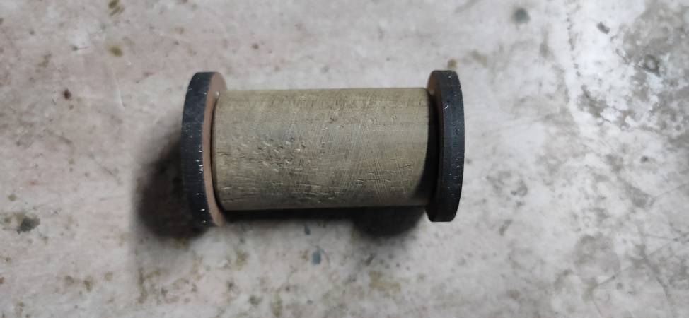
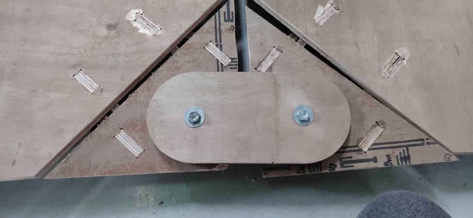
this is how the cylindrical log with the stopper for hinges looked like,
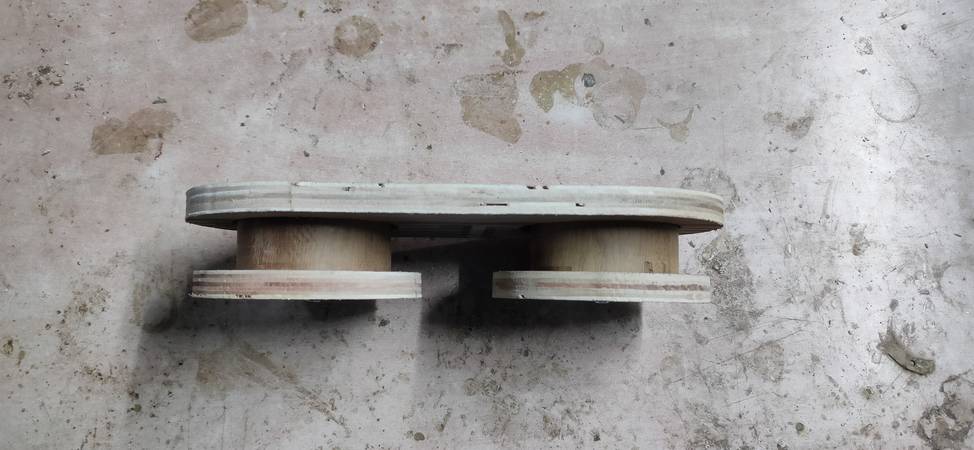
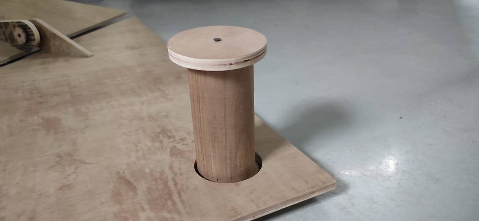
this is how the cylindrical log with the stopper for pivot point(door handle) looked like,
this is how the cylindrical log with the stopper for pivot point(on which the door will be mounted) looked like,
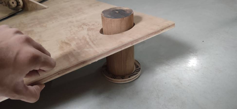
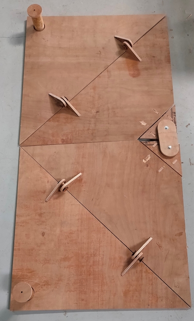
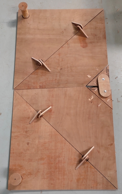
with the cylindrical log ready with stopper attached, i started inserting them into the hinges and pivot points of the door,
with all the cylindrical logs insterted into hinges and pivot point with stopper screwed on both ends, i tried to lift the door handle and the door handle came right off because there wasn't enough grip in the screws. I considered buying thicker screws but then i came up with the idea of useing bolt and nut, so i again drilled bigger hole in the stopper and cylidrical logs and then inserted them into the pivot point of the door handle. There was need to insert the bolt and nut just for the pivot point of the door handle since the stopper for hinges and the stopper for the pivot point on which the door is going to mount won't have to face this much pressure, the stopper was there just to avoid the hinge log and pivot log to slip out.
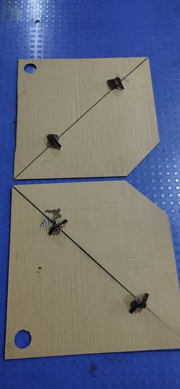
this is how the cylindrical logs are inserted into the hinges,
this is how the cylindrical logs are inserted into the pivot point of the door handle,
this is how the cylindrical logs are inserted into the pivot point on which the door will be mounted,
if you watch the last video, you'll observe that i was able to lift the door and the bolt and nut was doing its job of keeping the stopper and the log attached. However i was not able to fold the door around the hinges as i wanted,
a guy passing around the workshop told me that the two small triangle piece, where i have inserted the pivot point for door handle was clashing, so i removed a chunk of plywood from both the small triangle with the hacksaw. I somehow managed to cut straight on one piece and not-so-straight on the other piece,
even after cutting the small triangle, the door was still not folding! I then went to the lab and took out the prototype i made on the cardboard and it was then that i realised that i made a HUGE mistake! I was suppose to attach the hinges on the centre trapezpoid and the small triangle on the BACK of the door. Instead, i attached all the hinges on the front of the door!
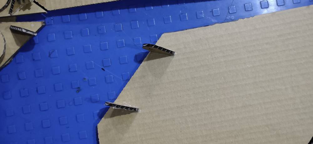
after realizing my mistake, i re-attached the hinges. Fortunately, the hinges came off with just pressure and i didn't need to cut the piece or whole part,
Here is the working of the door(not very smooth),
some heroshots,
Now the only task remains is fitting the door at the office. To do that we need to weld two pipes onto the metal frame, and through the pipe we need to insert the 3 inch diameter 6 inch length cylindrical rod and re-screw the stopper on both endes to prevent the door from sliding. I have currently left Vigyan Ashram after getting assurance from my local instructor that he'll help me by fitting the door into the office. Will update the documentation later if i get any response from my local instructor.
Drip Irritation by Fenil Chandarana is licensed under Attribution-NonCommercial-NoDerivatives 4.0 International![]()
![]()
![]()
![]()